Online power – OnLine Power Telecommunication User Manual
Page 36
OnLine Power
3-6
REV A
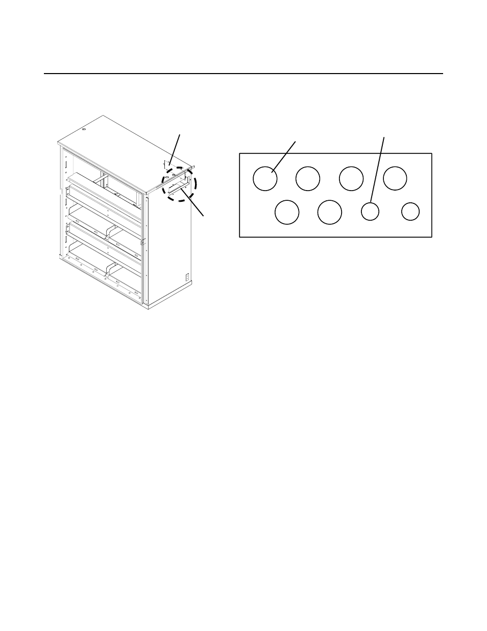
CONDUIT LANDING HATCH-PLATE
3/4" or 1" Conduit
1/2" Conduit Knock
Rear Hatch-Plate
Side Hatch-Plate
NOTE: The cabinet comes with
One pre-punched knockout hatch-plate installed
and One blank hatch-plate installed
Knock out holes
(typ. 6)
out holes (typ. 2)
CABINET CONDUIT LOCATION
ILLUSTRATION 3-2
3-9
PBC-II CONDUIT INSTALLATION
See Lucent Technical Installation Manual for details
3-10
ELECTRONIC TRAY WIRING
See Lucent Technical Installation Manual for details
3-11
INPUT & OUTPUT WIRING (TB1)
• Connect three (3) input power wires (No 12AWG or higher) at TB1-1, 2, and 3.
• Connect outputs #1 through #4 at TB1-4 through TB1-15 (as required)
• Connect TB1-16 through TB1-23 and Connector J13 to the optional Adjunct Battery Cabinet using
supplied interconnect kit as follows. Connector J13 and wiring at TB1-16 through TB1-23 is not
used, when the optional Adjunct Battery Cabinet is not used.