Online power, Appendix e: summary of all alarms and functions – OnLine Power Telecommunication User Manual
Page 56
OnLine Power
E-1
REV A
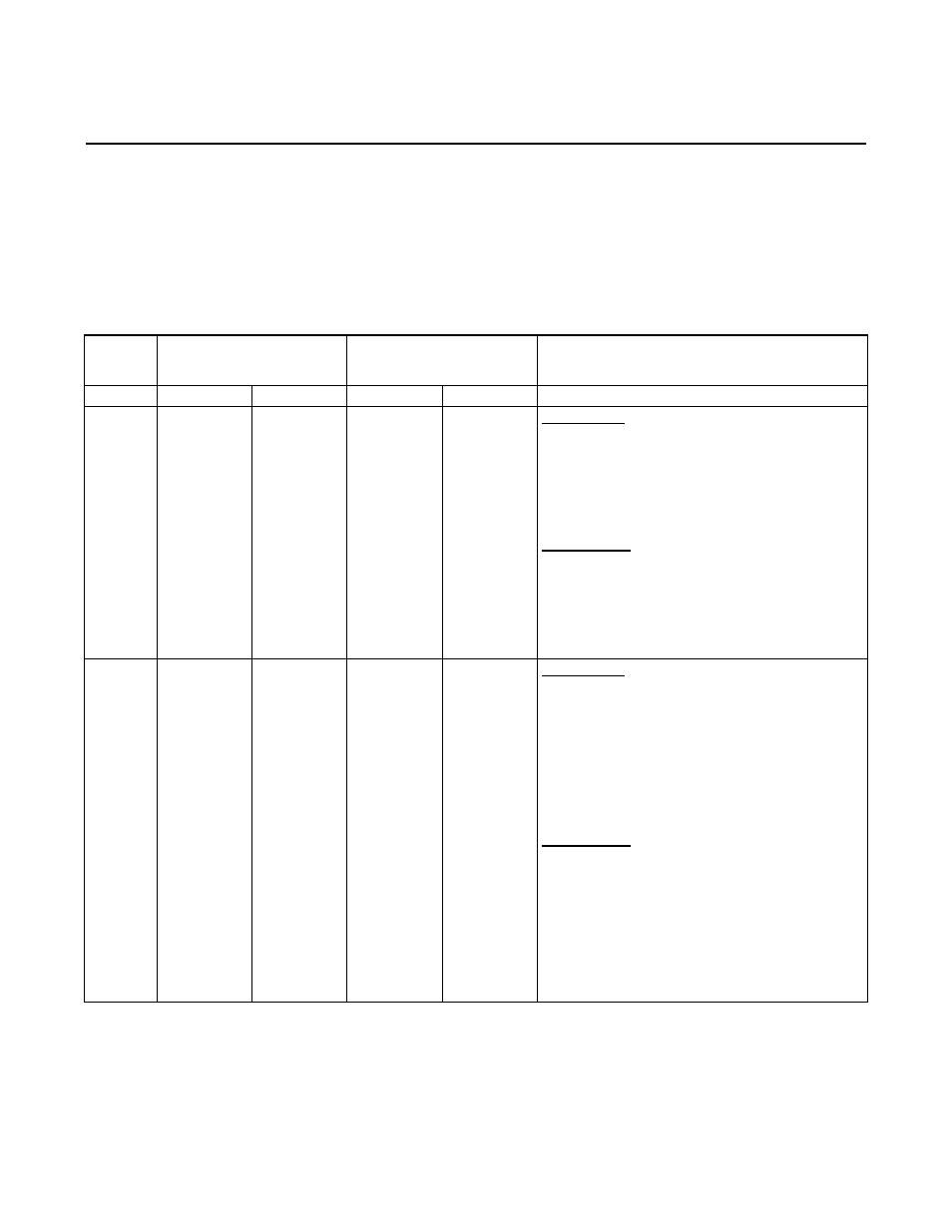
Appendix E: SUMMARY OF ALL ALARMS AND
FUNCTIONS
ALARM
CONDITIO
N
AC MODE
DC MODE
CUSTOMER ACTION
ALARMS OUTPUT ALARMS OUTPUT
Overtemp
erature
(above
90
0
C)
1) “Summary
Alarm” LED ON
2) “Bypass ON”
and AC INPUT
ON” LED ON
3) DB9
Connector (pin
3 to 5) contact
closes for
“Summary
Alarm”
1) Output is
NORMAL and
supplied from
UPS
2) Auto Bypass
circuit may
supply output
power, in case
of internal
failures
1) “Summary
Alarm” LED ON
2) “Bypass ON”
and AC INPUT
ON” LED is
OFF
3) DB9
Connector (pin
3 to 5) contact
closes for
“Summary
Alarm”
1) Not
Available
2) Unit is
shut-down
For AC MODE
1) Open the door. Remove the front dead panel. Pull the
electronic tray partially. Check wiring and temperature.
2) If all okay, put the unit back. Open & close all CBs.
3) Restart the unit to see if the unit is coming up normal.
4) If problem exists, replace electronic tray.
FOR DC MODE
1) Open the door. Remove the front dead panel. Pull the
electronic tray partially. Check wiring and temperature.
2) If all okay, put the unit back. Open & close all CBs.
3) Restart the unit by pressing S1 & S2 on the display
board to see if the unit is coming up normal.*
4) If the unit shuts down again, replace electronic tray.
Overload
At the
output
(over 120%
thru 160%
of nominal
output
load)
1) “Summary
Alarm” LED ON
2) “Overload”
LED ON
3) “Bypass”
LED OFF
4) DB9
Connector (pin
3 to 5) contact
closes for
“Summary
Alarm”
5) The unit
shut-down in
10-12 seconds.
1) Auto Bypass
circuit supplies
output power
2) Output CBs
may not trip, for
120% through
160%.
3) Output CBs
trip for over
160%.
1) “Summary
Alarm” LED ON
2) “Overload”
LED ON
3) DB9
Connector (pin
3 to 5) contact
closes for
“Summary
Alarm”
4) The unit
shuts down
5) “Bypass ON”
and AC INPUT
ON” LED is
OFF
No output
available
For AC MODE
1) Check “Overload” LED is ON.
2) OPEN all circuit breakers and restart the unit by closing
breakers CB1 and CB9, or by pressing S1 & S2 on the
display board.*
3) If “Overload” LED is still ON without output CB closed,
then replace the electronic tray.
4) Reduce the load if “Overload“ LED comes ON only with
output breaker closed and with load.
FOR DC MODE
1) Open all CBs and restart the unit by closing CB1 & CB9,
or by pressing S1 & S2 on the display board.*
2) Close output CB to see it “Overload” LED is still ON or
OFF.
3) If “Overload” LED is still ON, reduce the load.
4) Then open the Input CB to see “Overload” LED does not
comes ON.
5) If still “Overload” LED comes ON, then replace the
electronic tray.
* Hold S2 switch for 5 seconds to restart the PBC unit successfully from the display board.