D. assembly / disassembly, English - 5 c. safety equipment description, Attention – Partner P818 2014 User Manual
Page 15
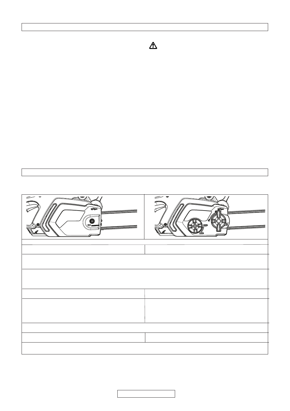
D. ASSEMBLY / DISASSEMBLY
BAR AND CHAIN ASSEMBL
Y
Assembly methods change according to the type of your machine- so please take care to refer to the illustrations and
machine type marked on the label. Take great care when assembling to ensure this is performed correctly.
1. Check that the chain brake is not activated. If so, deactivate it.
2a. Unscrew the bar retaining nut and remove the
2b. Unscrew the bar retaining knob and remove
drive sprocket cover.
the drive sprocket cover.
3 Position the chain over the bar, starting at the nose sprocket, fitting into the bar guide groove.
Attention!
Ensure that the sharp side of the cutting teeth face in a frontward direction on the upper part of the
bar. Wear Gloves.
4. Ensure the chain tensioner pin is as far back towards the drive sprocket as possible. Mount the bar on the
bar retaining screw and the chain tensioner pin and position the chain over the drive sprocket. Replace the
drive sprocket cover, ensuring the drive teeth of the chain are engaged in the drive sprocket and in the guide
groove.
5a. Screw the bar retaining nut by hand until loosely
5b. Screw the bar retaining knob until loosely
tightened.
tightened.
6a. To tension the chain, screw the chain tensioner
6b. To tension the chain, screw the chain
screw in a clockwise direction using the spanner/
tensioner outer knob in a clockwise direction.
screwdriver provided. To reduce tension screw in an
To reduce tension screw in an anti-clockwise
anti-clockwise direction when performing this operation,
direction. (when performing this operation,
( keep the bar nose raised upwards)
keep the bar nose raised upwards)
7. Tension the chain until the tension is correct. Pull the chain away from the bar and ensure gap measures
approx 2-3mm
8a. Tighten the bar retaining nut using the spanner/
8b. Tighten the bar until securely tightened.
screwdriver provided
Tensioning the chain too tightly will overload the motor and cause damage, insufficient tension can provoke chain
derailing, whereas a chain tightened correctly provides the best cutting characteristics and prolonged work life. Check
the tension regularly because the chain length tends to stretch with use (especially when the chain is new; after the
first assembly, the chain tension must be checked after 5 minutes machine operation); in any case do not tighten the
chain immediately after use, but wait until it cools down.
In cases where the loosened chain needs to be adjusted, always unscrew the bar retaining nut / knob before adjusting
the chain tensioning screw / knob; adjust the tension and tighten the bar retaining nut / knob accordingly.
ENGLISH - 5
C. SAFETY EQUIPMENT DESCRIPTION
SWITCH BLOCK
Your machine is equipped with a device
(fig.1)
that when
deactivated, stops the switch from being pressed thus
preventing accidental start-up.
CHAIN BRAKE ACTION ON SWITCH RELEASE
Your machine is equipped with a device that blocks the
chain immediately as soon as the switch is released; If
this device should not work at any time, the machine
must NOT be used and must be taken to an Authorised
Service Centre.
FRONT HAND GUARD / CHAIN BRAKE LEVER
The front hand guard
(fig.2)
is designed to prevent your
left hand from coming into contact with the chain (on
condition that the machine is held correctly according to
instructions). The front hand guard also acts as a chain
brake, including a device that blocks the chain in less
than 0.15 of a second in the case of kickback. The chain
brake is released when the front hand guard is pulled
backwards and clicked in position (the chain is able to
move). The chain brake is activated when the front hand
guard is pushed forward (the chain is blocked). The
chain brake can be activated using the left wrist by
pushing forwards, or when the wrist comes into contact
with the front hand guard as a result of kickback.
When the machine is used with the bar in horizontal
position, for example during tree felling, the chain brake
offers less protection.
(fig.3)
.
N.B.: When the chain brake is activated, a safety switch
cuts off all current to the motor.
Releasing the chain brake whilst the switch
is held will start the product.
CHAIN CATCHER
This machine is equipped with a chain catcher
(fig.4)
located under the sprocket. This mechanism is designed
to stop the backward chain movement in the case of
chain breaking or derailing. These situations can be
avoided by ensuring correct chain tension (Refer to
chapter “D. Assembly/disassembly”).
REAR HAND GUARD
This acts to protect
(fig.5)
the hand in the case of chain
breaking or derailing.