Teletronics WINC900A User Manual
Page 19
19
6.0 WINC 900A Interface Status
The WINC 900A interface status refers to the state of the RS-232 serial port between the local
terminal or computer and the WINC 900A. The state, in turn, is determined by the signal levels on
each of the signal lines that comprise the serial port. These status lines have been brought to the
front panel in the form of a series of eight (8) light emitting diodes (LED). In addition, a reset button
has been provided to the right of this series of LEDs.
To the right of the reset button are two additional indicators, one above the other and each
rectangularity shaped. When the unit is powered on, the upper indicator turns red and stays red until
the unit is powered down. The lower indicator provides a measure of the receive signal strength.
When the indicator is green, the receive signal on the current channel is sufficiently strong to
maintain a connection with the remote terminal. A weak signal will cause the indicator to turn off.
Each LED displays one of two different colors, green or red. Green indicates an active state or signal
presence, whereas red indicates an inactive state or signal absence. The table below indicates the
function of each signal beginning with RI, the left most indicator. The remaining indicators appear
from left to right ending with RXD, the right most indicator.
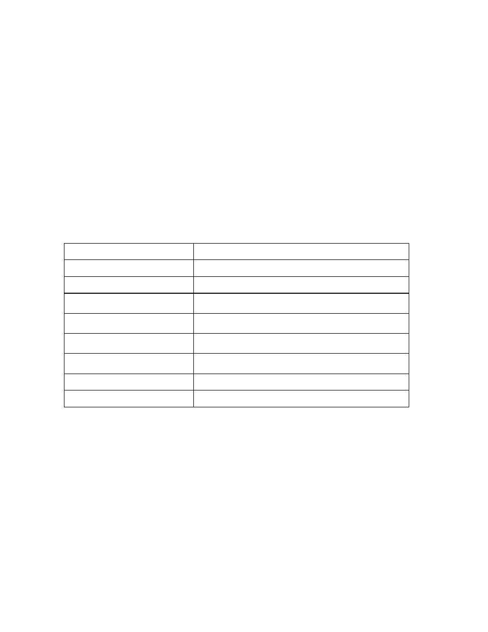
Panel L E D
Function
Ring Indicator (RI)
Signals incoming connection request.
Data Carrier Detect (DCD)
Indicates "connection established" with remote.
Data Terminal Ready (DTR)
Signal from host to device. May indicate command mode
escape or ignored by device.
Data Set Ready (DSR)
Signal from device to host. May indicate connection
established or always on.
Clear To Send (CTS)
Indicates device ready to accept data from host. Used in H/W
flow control.
Request To Send (RTS)
Indicates host ready to send data to device. Used in H/W flow
control.
Receive Data (RXD)
Serial data input to host from device.
Transmit Data (TXD)
Serial data input to device from host.
When the WINC 900A is initially powered up the CTS and DSR indicators should be green, whereas
the RI and DCD indicators are red.
Once the connection is established, the DCD indicator turns green.
If the system is configured to use hardware flow control the CTS indicator will change to RED when
the WINC's internal buffer becomes full. When data is removed from the buffer the CTS indicator
will turn green again.
When a connection request from a remote terminal is received the RI turns green. It will turn red
when the connection is established or the connection request has timed out.
The DTR, DSR, RTS, and CTS indicators follow the AT configuration commands as issued to the
WINC 900A. For example, if the device has been configured for S/W flow control then the RTS and
CTS indicators will be red.