Cfl-5000, L1 ► l2, Camera fiber-link – Thinklogical Camera Fiber-Link Manual User Manual
Page 12: L2 ◄ l1 ◄ l3
Extend Distribute Innovate
®
Camera Fiber-Link Extender Manual
8
Rev. E, June 2012
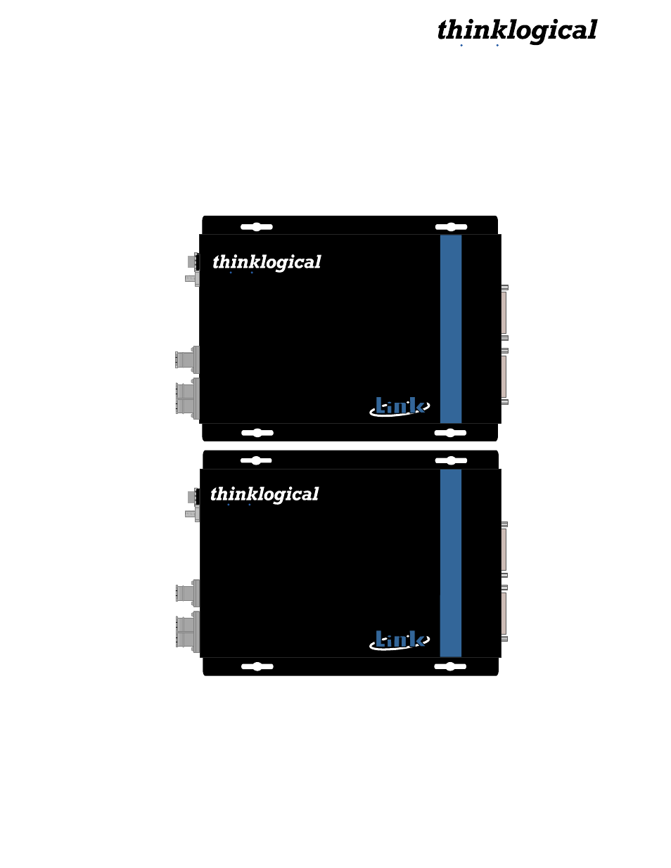
2.2.3 CFL-5000
The CFL-5000 Extender supports camera signals and serial connections (both the SerTFG and
SerTC within the MDR cable, and three pairs of RS-232 lines). The CFL-5000 supports one or two
base Camera-Link cameras or one dual-base Camera-Link camera configurations. Each unit is
housed in a compact, metal enclosure (7.
00” x 5.44” x 1.19”). The CFL-5000 is available with SC-
(standard), ST- or LC-type fiber optic connectors.
C A M E R A
L1
►
L2
►
S
E
R
IA
L
F
R
A
M
E
G
R
A
B
B
E
R
L3
◄
B
A
S
E
1
F
R
A
M
E
G
R
A
B
B
E
R
B
A
S
E
2
Digital Camera
Extension System CFL- 5000
HI-SPEED
BASE
FRAME GRABBER SIDE
DUAL
CAMERA FIBER-LINK
®
Extend Distribute Innovate
®
C A M E R A
C
A
M
E
R
A
1
S
E
R
IA
L
C
A
M
E
R
A
2
CAMERA FIBER-LINK
Digital Camera
Extension System CFL- 5000
CAMERA SIDE
HI-SPEED
BASE
DUAL
L2
◄
L1
◄
L3
►
®
Extend Distribute Innovate
®
Powered by
MRTS
Technology
Powered by
MRTS
Technology
Figure 4: CFL-5000 Camera Side (CFL-000M05-SCTX) and Frame Grabber Side (CFL-000M05-SCRX)
Each CFL-5000 configuration requires three fibers. The Camera Side Unit receives data from
each camera and converts the data into optical signals. These signals are sent to the CFL-5000
Frame Grabber Side Unit, which in turn converts the optical signals into video data and sends
them to the one dual-base frame grabber (CPU).