H3C Technologies H3C S12500 Series Switches User Manual
Page 11
3
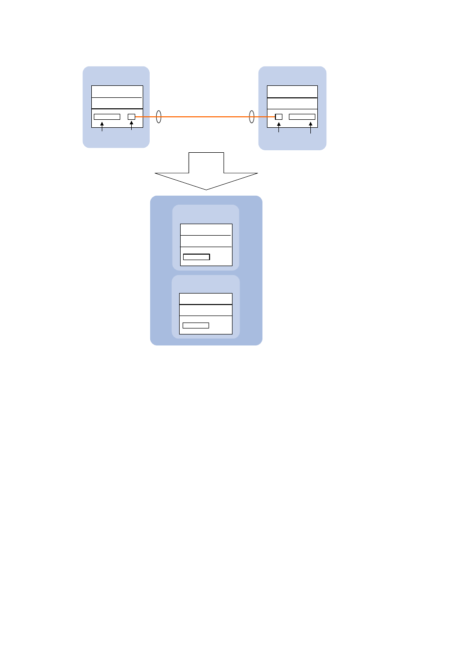
Figure 2 Two-chassis IRF fabric implementation schematic diagram
In this figure, Device A and Device B form a two-chassis IRF fabric that has four MPUs (one active and
three standbys) and two times the number of interface cards that a single device provides. The IRF fabric
manages both the physical and software resources of Device A and Device B in a centralized manner.
You can scale this two-chassis IRF fabric to a four-chassis IRF fabric for higher port density and
availability, as shown in
.
IRF link
An IRF fabric
is formed.
Master
(MemberID=1)
Subordinate
(MemberID=2)
Active MPU
Device A
(MemberID=1)
Device B
(MemberID=2)
XGE1/3/0/1
Physical IRF
port
XGE2/3/0/1
Physical IRF
port
IRF-port 2
IRF-port 1
Service
interface
Service
interface
IRF
Standby MPU
Active MPU
Standby MPU
IRF’s Active MPU
IRF’s standby MPU
IRF’s standby MPU
IRF’s standby MPU