Operating mode, Irf member roles – H3C Technologies H3C S12500 Series Switches User Manual
Page 12
4
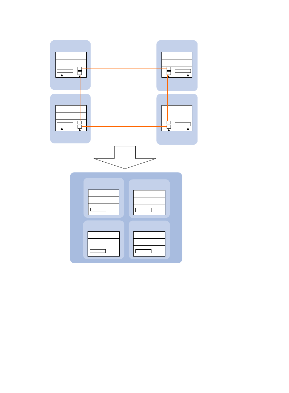
Figure 3 Four-chassis IRF fabric implementation schematic diagram
Operating mode
A device operates in one of the following modes:
•
Standalone mode—The device cannot form an IRF fabric with other devices.
•
IRF mode—The device can form an IRF fabric with other devices.
IRF member roles
IRF uses two member roles: master and slave (called "subordinate" throughout the documentation).
IRF link
IRF is
formed.
Master
Subordinate
IRF physical
ports
IRF physical
ports
IRF- port 2
IRF-port 1
Network
interfaces
Network
interfaces
IRF
Global active MPU
Global standby MPU
Global standby MPU
Global standby MPU
Active MPU
Device A
Device B
( Member ID=2 )
IRF-port 2
IRF-port 2
Network
interfaces
Network
interfaces
Standby MPU
Active MPU
Standby MPU
IRF- port 1
IRF physical
ports
IRF physical
ports
Active MPU
Standby MPU
Device C
Device D
Active MPU
Standby MPU
IRF-port 1
IRF-port 2
IRF- port1
Subordinate
Global standby MPU
Global standby MPU
Subordinate
Global standby MPU
Global standby MPU
( Member ID=4 )
( Member ID=1 )
( Member ID=3 )
( Member ID=2 )
( Member ID=1 )
( Member ID=3 )
( Member ID=4 )