Configuration procedure – H3C Technologies H3C S12500 Series Switches User Manual
Page 57
49
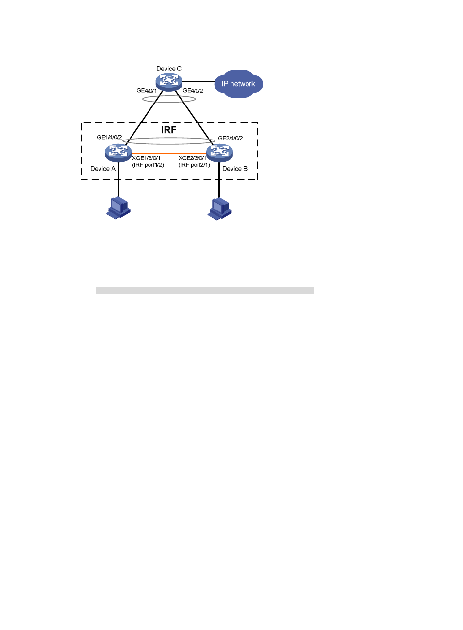
Figure 20 Network diagram
Configuration procedure
1.
Identify the master.
<IRF> display irf
Switch Slot Role Priority CPU-Mac Description
*+1 0 Master 1 00e0-fc0a-15e0 DeviceA
1 1 Slave 1 00e0-fc0f-8c02 DeviceA
2 0 Slave 1 00e0-fc0f-15e1 DeviceB
2 1 Slave 1 00e0-fc0f-15e2 DeviceB
--------------------------------------------------
* indicates the device is the master.
+ indicates the device through which the user logs in.
The Bridge MAC of the IRF is: 000f-e26a-58ed
Auto upgrade : no
Mac persistent : always
Domain ID : 0
The output shows that Device A is the master.
2.
Examine the configuration for VLAN interfaces.
If a VLAN interface has member ports on different member devices, change the IP address for the
VLAN interface on each device to be unique after their operating mode is changed to standalone.
3.
Shut down IRF physical ports to disconnect all IRF links. In this example, shut down
Ten-Gigabitethernet 1/3/0/1.
<IRF> system-view
[IRF] interface ten-gigabitethernet 1/3/0/1
[IRF-Ten-Gigabitethernet1/3/0/1] shutdown
[IRF-Ten-Gigabitethernet1/3/0/1] quit
4.
Save the configuration.
[IRF] save
The current configuration will be written to the device. Are you sure? [Y/N]:y