S5820x-26s panel views, Front panel, Rear panel – H3C Technologies H3C S5820X Series Switches User Manual
Page 14
4
S5820X-26S panel views
Front panel
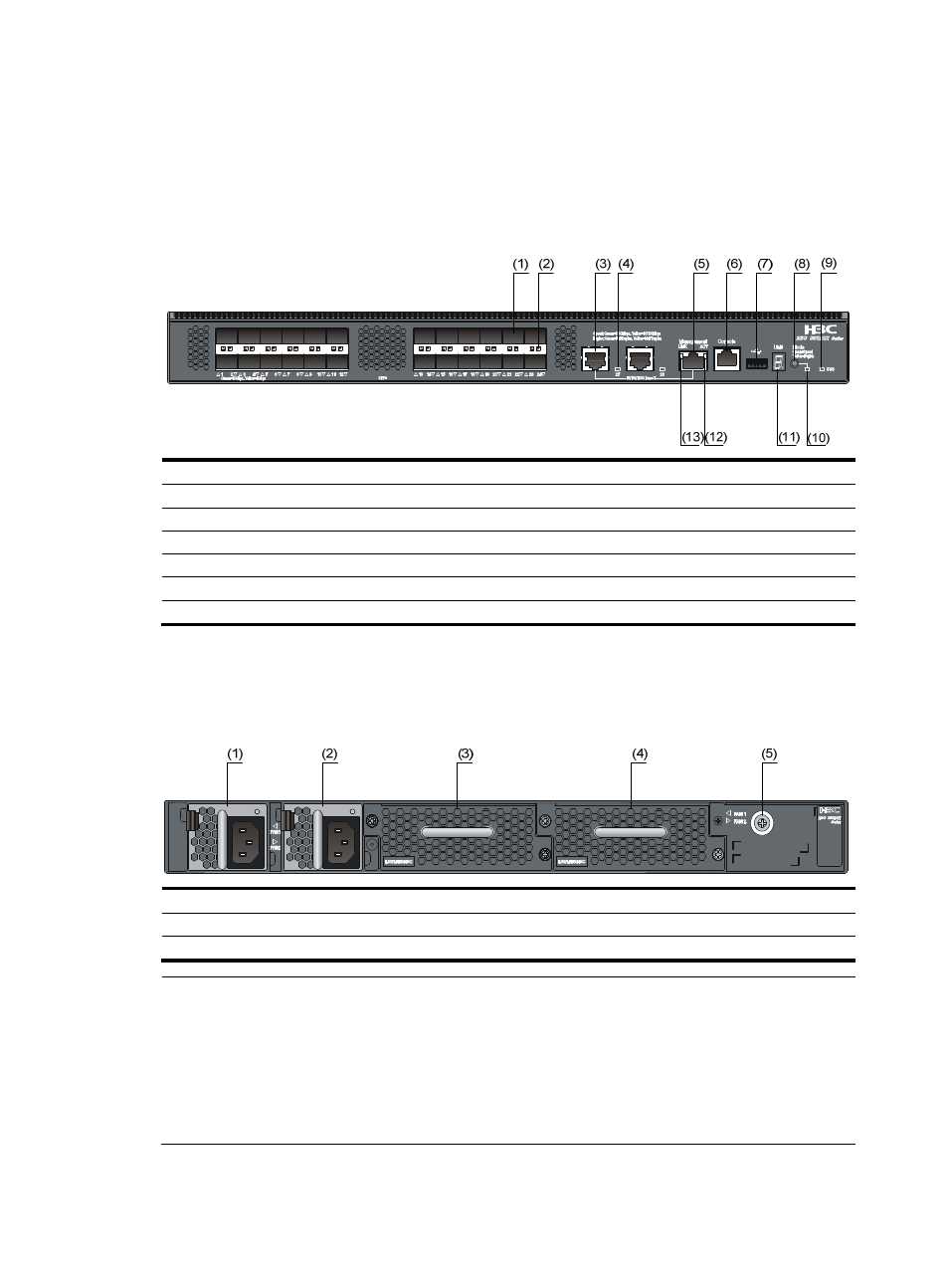
Figure 1 S5820X-26S front panel
(1) SFP+ port
(2) SFP+ port LED
(3) 10/100/1000Base-T auto-sensing Ethernet port
(4) 10/100/1000Base-T Ethernet port LED
(5) Management Ethernet port
(6) Console port
(7) USB port
(8) Port LED mode switching button
(9) System status LED (SYS)
(10) Port mode LED
(11) Seven-segment LED
(12) ACT LED for the management Ethernet port
(13) LINK LED for the management Ethernet port
Rear panel
Figure 2 S5820X-26S rear panel
(1) Power module slot 1
(2) Power module slot 2
(3) Fan tray slot 1
(4) Fan tray slot 2
(5) Grounding screw (auxiliary grounding point 2)
NOTE:
•
The S5820X-26S switch comes with the power module slots empty and the power filler modules as
accessories. You can install one or two power modules for your S5820X-26S switch as needed. In this
figure, two LSVM1AC650 AC power modules are installed.
•
The switch also comes with the fan tray slots empty. You must install two fan trays for the S5820X-26S for
adequate heat dissipation, and their models must be the same. In this figure, two LSWM1FANSC fan
trays are installed.