Left side panel, S5820x-28s panel views, Front panel – H3C Technologies H3C S5820X Series Switches User Manual
Page 15
5
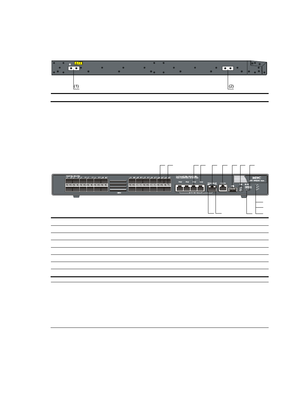
Left side panel
Figure 3 S5820X-26S left side panel
(1) Primary grounding point
(2) Auxiliary grounding point 1
S5820X-28S panel views
Front panel
Figure 4 S5820X-28S front panel
(1) SFP+ port
(2) SFP+ port LED
(3) 10/100/1000Base-T auto-sensing Ethernet port
(4) 10/100/1000Base-T Ethernet port LED
(5) Management Ethernet port
(6) Console port
(7) USB port
(8) Seven-segment LED
(9) Port mode LED
(10) System status LED (SYS)
(11) Power supply 1 status LED (PWR1)
(12) Power supply 2 status LED (PWR2)
(13) Port LED mode switching button
(14) ACT LED for the management Ethernet port
(15) LINK LED for the management Ethernet port
NOTE:
•
The SFP+ ports are numbered from left to right and from top to bottom, with you facing the front panel.
The first top left SFP+ port is numbered 1, the first bottom left SFP+ port is numbered 2, the second top
left port is numbered 3, and so on.
•
The 10/100/1000Base-T auto-sensing Ethernet ports, from left to right, are numbered 25, 26, 27, and
28.
(2)
(1)
(4)
(3)
(5)
(6)
(8)
(7)
(10)
(11)
(13)
(14)
(15)
(9)
(12)