S5820x-28s cooling system, S5820x-28c cooling system – H3C Technologies H3C S5820X Series Switches User Manual
Page 30
20
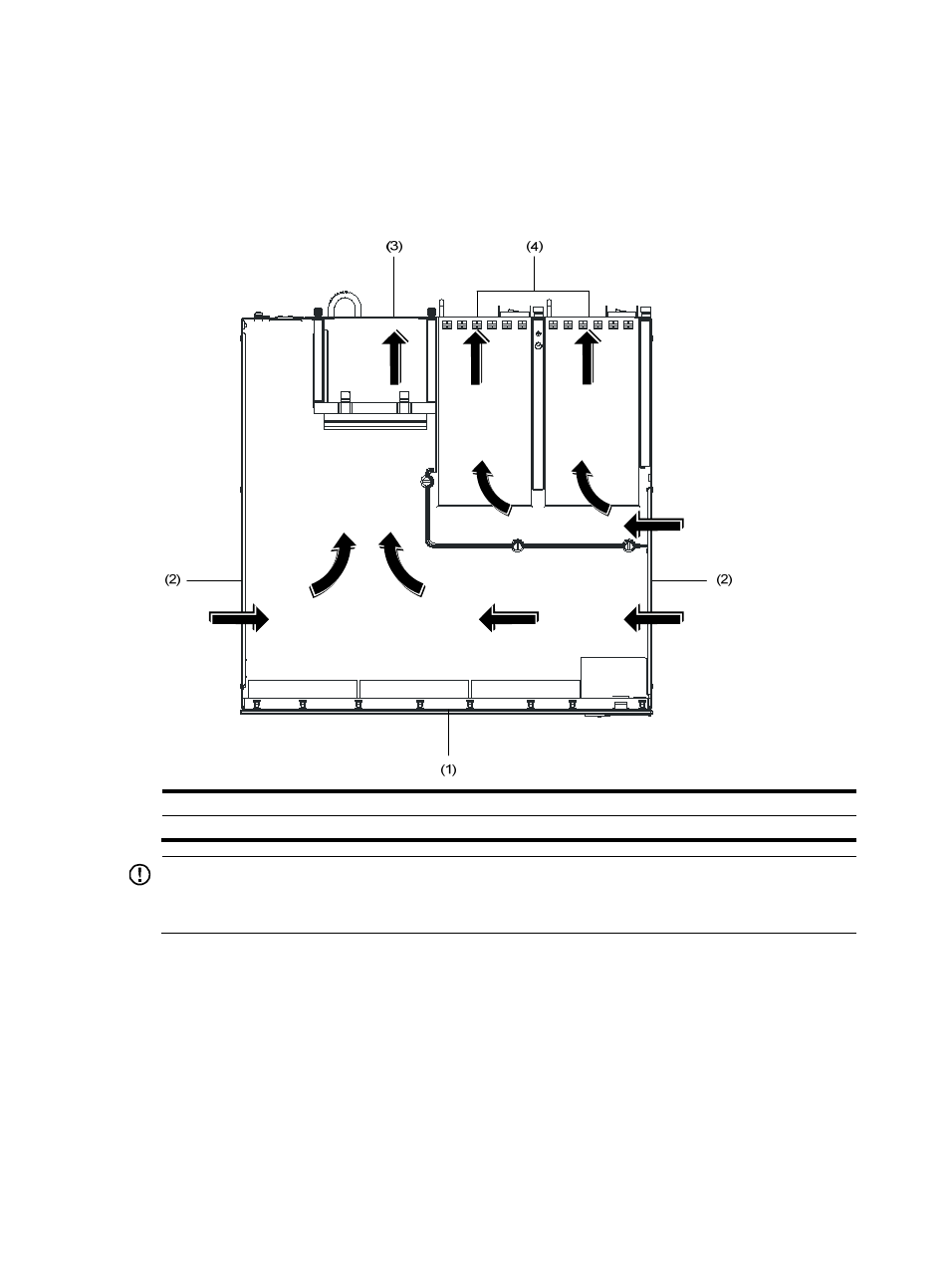
S5820X-28S cooling system
shows the airflow through the S5820X-28S chassis and power modules. Ambient air flows in
from the two sides of the chassis, circulates through the chassis and power modules, and exhausts
through the air vents in the fan tray panel and the power module panels.
Figure 13 Airflow through the S5820X-28S chassis
(1) Front panel
(2) Side inlet air vents
(3) Outlet air vents in the fan tray panel
(4) Outlet air vents in the power module panels
IMPORTANT:
The chassis and the power modules use separate air aisles. Make sure that both aisles have good
ventilation.
S5820X-28C cooling system
The S5820X-28C switch chassis is 2U high and uses separate air aisles for its upper half and lower half.
Make sure that the two air aisles have good ventilation.
•
shows the airflow through the lower half of the chassis. Ambient air flows in from the left
side of the chassis, circulates through the lower half of the chassis and the power modules, and
exhausts through the air vents in the fan tray panel and the power module panels.
•
shows the airflow through the upper half of the chassis. Ambient air flows in from the left
side of the chassis, circulates through the upper half of the chassis, including the OAP card and the
interface card, and exhausts through the outlet air vents in the fan tray panel.