Attaching the, Mounting brackets and, Chassis rails to the switch – H3C Technologies H3C S5820X Series Switches User Manual
Page 41: Chassis, Attaching the mounting, Brackets and chassis rails to the, Switch chassis
31
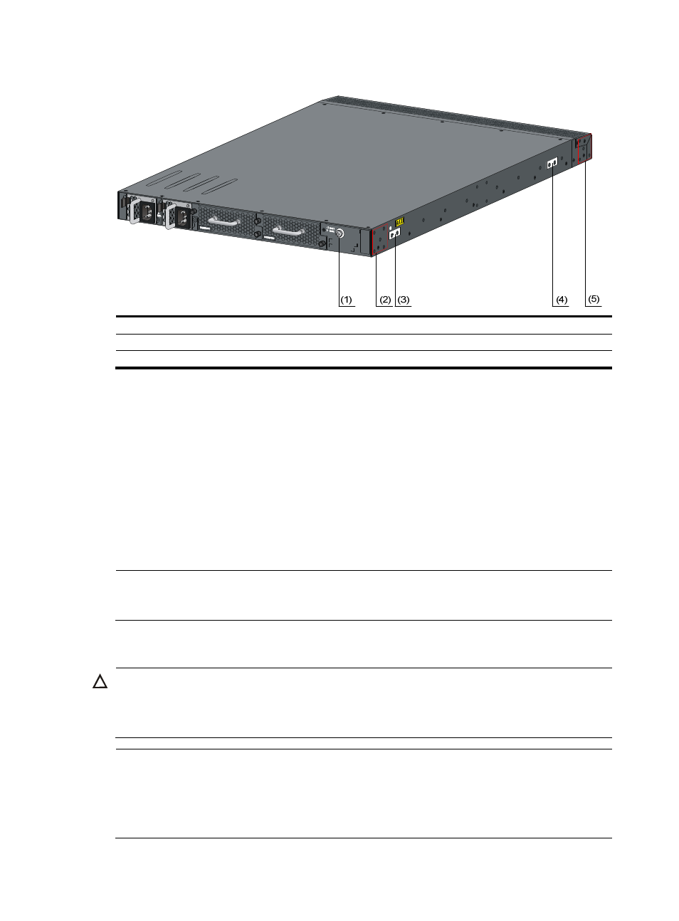
Figure 23 Identify the mounting and grounding positions
(1) Auxiliary grounding point 2
(2) Rear mounting position
(3) Primary grounding point
(4) Auxiliary grounding point 1
(5) Front mounting position
Attaching the mounting brackets and chassis rails to the switch chassis
To attach the mounting brackets and chassis rails to the switch chassis:
1.
Align the mounting brackets with the screw holes in the rear mounting position (see
) or
front mounting position (see
2.
Use M4 screws (supplied with the switch) to fix the mounting brackets to the chassis.
3.
If the mounting brackets are in the rear mounting position, align the chassis rails with the screw
holes at the front of the side panels (see
). If the mounting brackets are in the front
mounting position, align the chassis rails with the screw holes at the rear of the side panels
(see
4.
Use M4 screws (supplied with the switch) to fix the chassis rails to the chassis.
NOTE:
You secure the mounting brackets and chassis rails to both sides of the chassis in the same way.
Connecting the grounding cable to the switch chassis
CAUTION:
The primary grounding point and auxiliary grounding point 1 are located on the left side panel. If you use
one of these grounding points, you must connect the grounding cable to the grounding point before you
mount the switch in the rack.
NOTE:
•
H3C recommends that you use the primary grounding point or auxiliary grounding point 1 because the
grounding cable and grounding screw provided with the switch are applicable only to these two
grounding points.
•
To use auxiliary grounding point 2, you must prepare a grounding cable yourself.