Cabling, Video inputs – Grass Valley 8985FS v.1.2.0 User Manual
Page 19
8985FSP/FS/PRC — Instruction Manual
19
Installation
Cabling
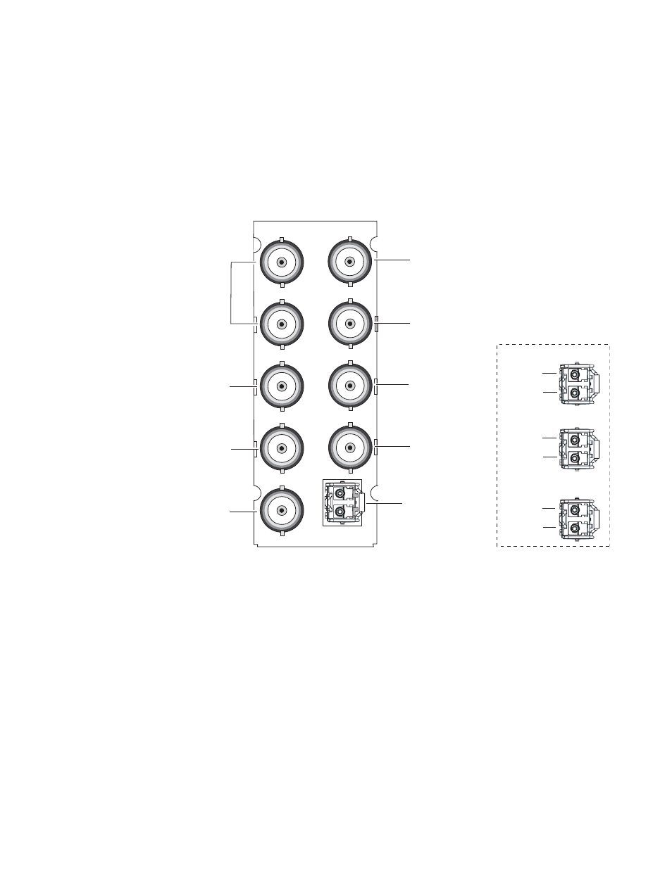
Cabling is done on the rear BNCs of the 8900GFR-R module illustrated in
. Inputs and outputs are also illustrated on the I/0 Config web page
I/O Config Web Page on page 38
Note
It is recommended to clean the fiber optic cable connectors with a lint-free,
anti-static cloth before making a connection to the fiber optic submodule.
Figure 7. 8900GFR-R Rear Module
Video Inputs
Connect an HD or SD digital video signal to the Coax input at BNC J9,
and/or to one or both of the fiber inputs at fiber connector J10 (depending
on the type of fiber submodule installed).
Note
Refer to
for important video input and external genlock
reference input video frame rate compatibility information.
For fiber optic inputs, the 1310-DRL or 1310-TRL SFP optical submodule
must be installed. Fiber inputs must be enabled with remote controls. Only
one video input can be used at a time and must also be selected with remote
controls.
8431_02r1
8900GFR-R
Fiber Optic Cabling
FIBER
J1
J2
J3
J4
J5
J6
J7
J9
J8
J1 and J3:
Genlock Loop
J9: Coax In
J5: SDI Out
Fiber Rx 1
Fiber Tx 2
Fiber Rx 2
J7: SDI Out
J8: SDI Out
Fiber Inputs/Outputs
(See Fiber Optic Cabling
at right.)
J6: SDI Out
J2: Auto Tracking
Delay Output
J4: Auto Tracking
Delay Output
1310NM-DRL
Fiber Tx 1
Fiber Rx 1
Fiber Tx 2
1310NM-DTL
1310NM-TRL