Control center block diagrams – Grass Valley CONTROL Center CameraMan Rev.B User Manual
Page 10
Install Your CONTROL Center
Page 7
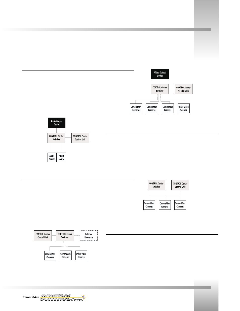
CONTROL Center Block Diagrams
Video I/O Connections
Input/output video connections from the Switcher rear panel to one or more devices are made
either by 75 Ohm coaxial cable terminated by BNC connectors(CV Model) or with S-video cable
terminated by mini-DIN connectors(SV Model).
Audio I/O Connections
Audio connections to one or more audio sources use cables with “Phoenix”- type connectors at
the Switcher.
Camera Control Connections
Camera Control connections from the Control Unit to CameraMan cameras use
RS-485 communication cables terminated by modular handset plugs. RS-485 “T”- style
connectors, or on some cameras, dual RS-485 ports, are used to daisy-chain up to 8 cameras
into a network.
Synchronizing Connections
Genlock connections from the Switcher to input sources are made with 75 Ohm coaxial cable
terminated by BNC connectors.
The following block diagrams explain how the CameraMan CONTROL Center connects to your cameras, video, audio, and external
synchronizing sources.