Cameraman and control center setup – Grass Valley CONTROL Center CameraMan Rev.B User Manual
Page 26
Customize Your CONTROL Center
Page 23
CameraMan and CONTROL Center Setup
Setting Up Multiple-Camera Systems: Addresses & dip switches
1. Set the BASE UNIT ADDRESS and dip switches on each camera in your network. The
CameraMan CONTROL Center automatically numbers the CameraMan cameras in your
network from 1 to 8. This corresponds to addresses 0–7 on the CameraMan base unit
and to the video inputs on the Switcher. Therefore, set the base unit address of the
cameras as follows:
On the back-right side of the camera are two banks of dip switches. On the bank near
the center of the camera, switch 7 and 8 must be in the UP position (towards the top
of the camera).
For details on changing your CameraMan camera’s base unit address, see the
installation and operations manual that came with your CameraMan System.
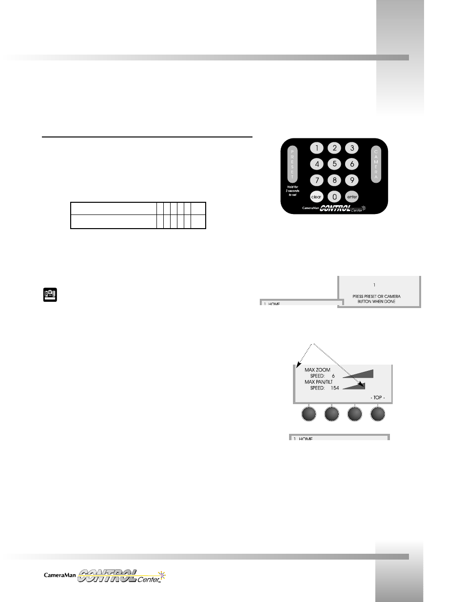
2. Choose the camera you want to configure. On the numeric keypad:
• Press the number of the camera you wish to configure (the LCD displays the
camera selection screen).
• Press
CAMERA (the LCD verifies the camera selected).
• Verify that the Home menu indicates the camera you selected.
3. Begin setting up each camera using the SETUP menus.
After powering up your system, the next step is to set up the CONTROL Center to work with the cameras in your system.
Camera Number:
1 2 3 4 5 6 7 8
Camera Base Unit Address:
0 1 2 3 4 5 6 7
On the keypad, enter the camera number desired,
then press the CAMERA button.
Note the camera # selection and verification screens, and that
the camera number shows on the indicator screen.