Connecting your audio, Page 10 – Grass Valley CONTROL Center CameraMan Rev.B User Manual
Page 13
Page 10
Installation and Operations Manual
Connecting Your Audio
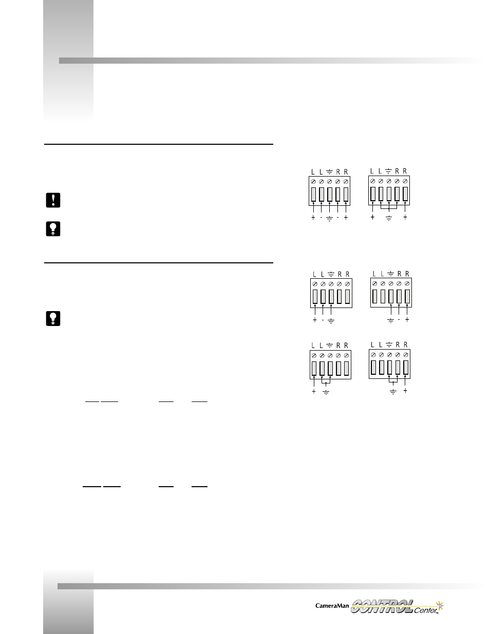
Switcher Audio Connections
The Switcher audio inputs will accept either balanced or unbalanced audio (mono or stereo).
Connect all inputs using the 5-position Phoenix connectors, according to the appropriate wiring
diagram.
If using audio from a CameraMan Presenter camera, the audio must be connected to
the same input number to which the video is connected.
It is usually easier to unplug the connector, make the wiring connections, and then
plug in the connector.
Switching Relationships
Any of the 8 audio inputs can be switched to any of the 4 audio outputs. However, when
switching video, there is, by default, a direct one-to-one relationship between audio and video
inputs (i.e. audio follows video). If desired, this relationship can be changed (refer to page 20).
For best results, connect each input source’s video and audio to the same input
number on the switcher. Do the same for each output source.
The chart below is an example of how to connect a typical system with one Presenter camera,
two General Pan/Tilt cameras, a VTR, and laser disc player used as video/audio inputs. In
addition, two program monitors, a VTR, and a preview monitor are used as video/audio
outputs.
Input Source
Video
Audio
Presenter Camera . . . . . . . . . .Input 1
Input 1
General P/T Camera . . . . . . . . . .Input 2
NA
General P/T Camera . . . . . . . . . .Input 3
NA
VTR . . . . . . . . . . . . . . .Input 4
Input 4
Laser Disc . . . . . . . . . . . . .Input 5
Input 5
Output Source
Video
Audio
Program Monitor 1 . . . . . . . . . .Output 1
Output 1
Program Monitor 2 . . . . . . . . . .Output 2
Output 2
VTR . . . . . . . . . . . . . . .Output 3
Output 3
Preview Monitor . . . . . . . . . . .Preview
Preview
STEREO Audio Wiring
Balanced
Unbalanced
MONO Audio Wiring
Balanced
or
Unbalanced
or