System configuration example – Yaskawa MP2000iec User Manual
Page 37
11 MECHATROLINK-II
YASKAWA America, Inc. MP2300iec Hardware Manual YAI-SIA-IEC-2R
37
MECHATROLINK-II Connectors CN1 and CN2
The Master-side MECHATROLINK-II network and the extended line of MECHATROLINK-II network are connected
via MECHATROLINK-II connection port connectors CN1 and CN2 on the REP2000.
Power Supply Connector
Connect an external +24 VDC power supply to the power supply connector.
DIP Switch
The DIP switch is for future use. All pins should be set to OFF.
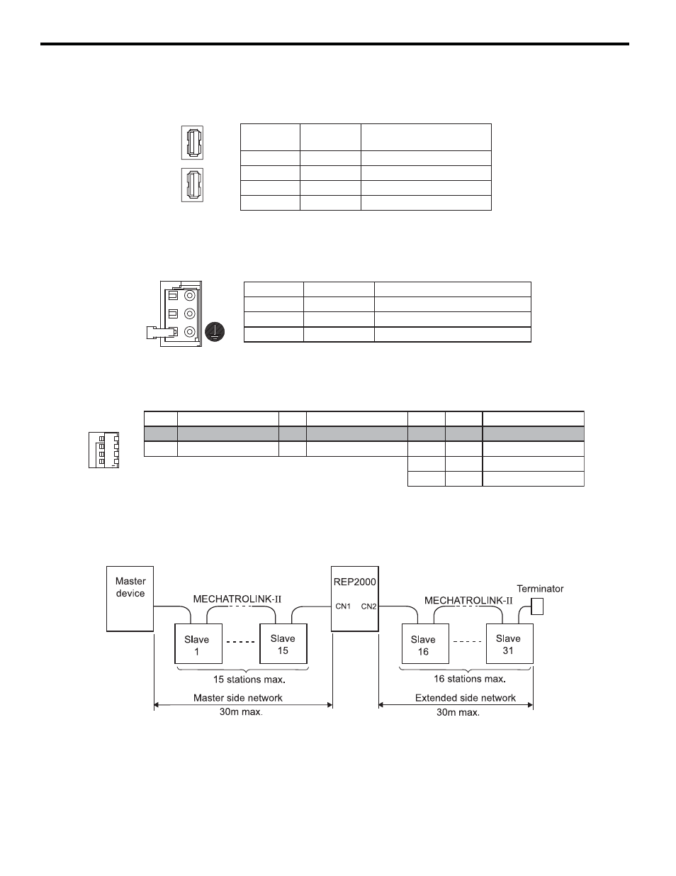
System Configuration Example
The figure below shows the configuration example of MECHATROLINK-II network system with a REP2000.
For 30m Maximum Extension of Network Distance
Pin No.
Signal
Name
Description
1
(NC)
Disconnected
2
/S
MECHATROLINK-II
3
S
MECHATROLINK-II
4
FG
Frame ground
CN1
CN2
Pin No.
Signal Name
Description
1
FG
Frame ground
2
024V
0 VDC input
3
+24V
24 VDC input
CN3
DC24V
DC 0V
OP
Function
SP
Function
D2
D1
Function
OFF
None (Factory setting) OFF
None (Factory setting) OFF
OFF
None (Factory setting)
ON
None
ON
None
OFF
ON
None
ON
OFF
None
ON
ON
None
SW
OP
SP
D2
D1
1
O
N