Voltage supply rise time, Using the buffer empty (be) line, Using the exception (ex) line – Linx Technologies TRM-915-R250 User Manual
Page 14: Using the processing incoming packet (pr_pkt) line, Receive signal strength indication (rssi)
– –
– –
22
23
Voltage Supply Rise Time
The power supply rise time is extremely important. It must rise from ground
to 2.7V in less than 1ms. If this specification cannot be met, an external
reset supervisor circuit must be used to hold the module in reset until the
power supply stabilizes. Failure to ensure adequate power supply rise time
can result in loss of important module configuration information.
Using the Buffer Empty (BE) Line
The BE line indicates the state of the module’s UART buffer. When the
module receives data in the RXD line and the CMD line is high, the BE line
is lowered until all data in the buffer has been processed by the protocol
engine. If acknowledgement is not enabled, the BE line is raised as soon as
the protocol engine processes the outgoing packets. If acknowledgement
is enabled, the buffer is not updated until either the data transmissions
are acknowledged by the remote end or delivery fails after the maximum
number of retries. When the BE line returns high, the EX line may be
sampled, or the regEXCEPTION register polled to determine if an error
occurred during transmission.
Using the Exception (EX) Line
The EX line indicates whether or not a module exception has occurred.
The line is normally low, but it is raised if an exception occurs that passes
masking. When the regEXCEPTION register is read, the exception is
cleared and the EX line returns low. If more than one exception occurs
before the regEXCEPTION register is read, the old exception is overwritten
by the new one. Please see the Exception Engine section for more details.
Using the Processing Incoming Packet (PR_PKT) Line
The PR_PKT line indicates whether the protocol engine has determined
there to be valid or potentially valid data incoming. The line is normally low
(not processing). When awake and not transmitting, the protocol engine
is constantly searching for incoming data. When scoring indicates that a
potential packet is inbound, this line is raised until either the scoring falls
below a given threshold or the complete packet is received. It is possible
that the packet scoring will fall below the threshold during reception,
causing the line to be lowered. Such an instance can occur when the
module hops to a channel late in the transmitter’s extended preamble.
Since there aren’t a large number of valid bits to score, the line may fall
during the packet start sequence. Once this sequence arrives, the PR_PKT
signal rises and latches for the duration of the packet reception.
Receive Signal Strength Indication (RSSI)
The RSSI line outputs an analog voltage that is proportional to the signal
strength present on the channel at the time. In normal operation, the
module is hopping rapidly from channel to channel. In this case, the
RSSI value varies greatly and does not provide much useful information.
However, it can be used to keep a module awake by sampling the RSSI
line to determine if the module is processing a packet before putting it to
sleep.
The 250 Series module has an internal digital RSSI indication of the
immediate ambient environment and of the last good packet received.
Additionally, the PR_PKT line can be used to indicate the state of the
protocol engine.
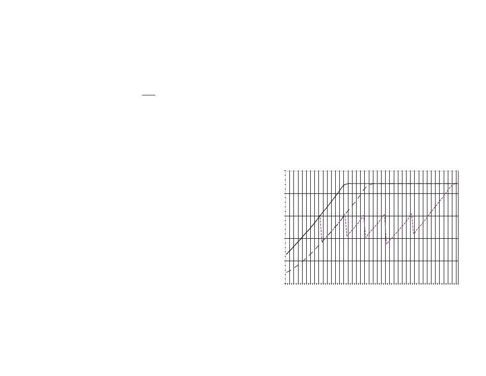
RSSI level is dependent on the power of the signal received at the antenna
port and the mode the LNA is in. regLNAMODE controls the mode of the
internal LNA. Figure 16 shows typical traces of RSSI voltage versus signal
strength.
0
500
1000
1500
2000
2500
-102 -98 -94 -90 -86 -82 -78 -74 -70 -66 -62 -58 -54 -50 -46 -42 -38 -34 -30 -26 -22
RF IN (dBm)
RSSI OUT (mV)
High Sens
Mid IIP3
High IIP3
Auto Gain
Figure 16: 250 Series Transceiver P
IN
vs RSSI Voltage