Interference considerations, Microstrip details – Linx Technologies TRM-915-R250 User Manual
Page 33
– –
– –
60
61
Interference Considerations
The RF spectrum is crowded and the potential for conflict with unwanted
sources of RF is very real. While all RF products are at risk from
interference, its effects can be minimized by better understanding its
characteristics.
Interference may come from internal or external sources. The first step
is to eliminate interference from noise sources on the board. This means
paying careful attention to layout, grounding, filtering and bypassing in
order to eliminate all radiated and conducted interference paths. For
many products, this is straightforward; however, products containing
components such as switching power supplies, motors, crystals and other
potential sources of noise must be approached with care. Comparing your
own design with a Linx evaluation board can help to determine if and at
what level design-specific interference is present.
External interference can manifest itself in a variety of ways. Low-level
interference produces noise and hashing on the output and reduces the
link’s overall range.
High-level interference is caused by nearby products sharing the same
frequency or from near-band high-power devices. It can even come from
your own products if more than one transmitter is active in the same area.
It is important to remember that only one transmitter at a time can occupy
a frequency, regardless of the coding of the transmitted signal. This type of
interference is less common than those mentioned previously, but in severe
cases it can prevent all useful function of the affected device.
Although technically not interference, multipath is also a factor to be
understood. Multipath is a term used to refer to the signal cancellation
effects that occur when RF waves arrive at the receiver in different phase
relationships. This effect is a particularly significant factor in interior
environments where objects provide many different signal reflection paths.
Multipath cancellation results in lowered signal levels at the receiver and
shorter useful distances for the link.
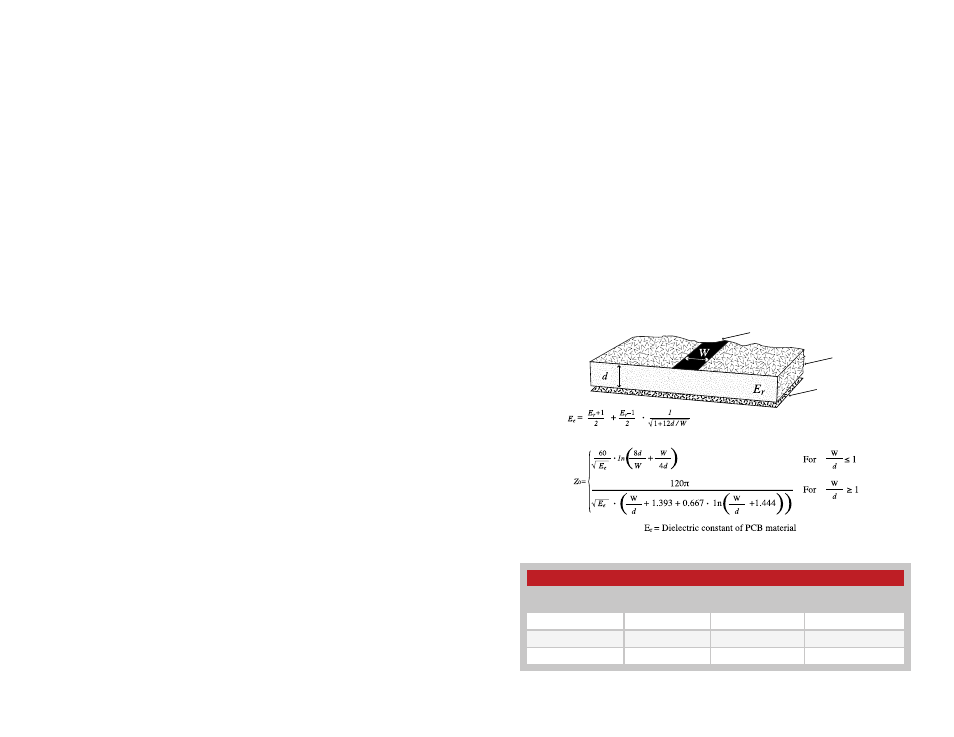
Microstrip Details
A transmission line is a medium whereby RF energy is transferred from
one place to another with minimal loss. This is a critical factor, especially
in high-frequency products like Linx RF modules, because the trace
leading to the module’s antenna can effectively contribute to the length
of the antenna, changing its resonant bandwidth. In order to minimize
loss and detuning, some form of transmission line between the antenna
and the module should be used unless the antenna can be placed very
close (<1/8in) to the module. One common form of transmission line is a
coax cable and another is the microstrip. This term refers to a PCB trace
running over a ground plane that is designed to serve as a transmission line
between the module and the antenna. The width is based on the desired
characteristic impedance of the line, the thickness of the PCB and the
dielectric constant of the board material. For standard 0.062in thick FR-4
board material, the trace width would be 111 mils. The correct trace width
can be calculated for other widths and materials using the information in
Figure 77 and examples are provided in Figure 78. Software for calculating
microstrip lines is also available on the Linx website.
Trace
Board
Ground plane
Figure 77: Microstrip Formulas
Example Microstrip Calculations
Dielectric Constant
Width / Height
Ratio (W / d)
Effective Dielectric
Constant
Characteristic
Impedance (Ω)
4.80
1.8
3.59
50.0
4.00
2.0
3.07
51.0
2.55
3.0
2.12
48.8
Figure 78: Example Microstrip Calculations