Regexception, Reglgprssi, Regimmedrssi – Linx Technologies TRM-915-R250 User Manual
Page 31: Regcustid[1
– –
– –
56
57
Last Good Packet RSSI - Address = 0x7B
This register holds the received signal strength in dBm of the last
successful received packet. A successful packet reception is one that
causes payload data to be output on the UART interface. The value in this
register is overwritten each time a new packet is successfully processed.
The register value is an 8-bit signed integer representing the RSSI in dBm.
It is accurate to ±3dB and has ±2dB linearity. The values take the LNA gain
into account.
Immediate RSSI - Address = 0x7C
This register returns the current receive signal strength indication in dBm.
The signal strength is measured as soon as the command is registered and
the value is loaded into the regIMMEDRSSI register. The register value is an
8-bit signed integer representing the RSSI in dBm. It is accurate to ±3dB
and has ±2dB linearity. The values take the LNA gain into account.
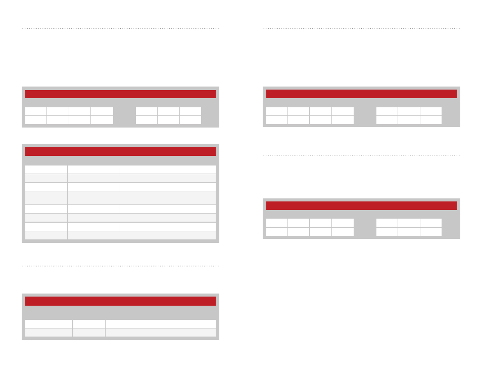
Figure 71: 250 Series Transceiver Last Good Packet RSSI Command and Response
Figure 72: 250 Series Transceiver Immediate RSSI Command and Response
250 Series Last Good Packet RSSI
Read Command
Read Response
Header
Size
Escape Address
ACK
Address
Value
0xFF
0x02
0xFE
0x7B
0x06
0x7B
V1
250 Series Immediate RSSI
Read Command
Read Response
Header
Size
Escape Address
ACK
Address
Value
0xFF
0x02
0xFE
0x7C
0x06
0x7C
V1
Exception - Address = 0x79
The module has a built-in exception engine that can notify the host
processor of an unexpected event. If an exception occurs, the exception
code is stored in this register. Reading from this register clears the
exception and, if applicable, resets the EX line. If an exception occurs
before the previous exception code is read, the previous value is
overwritten. Figure 68 shows examples of the commands and Figure 69
shows the available values.
Custom ID
These registers contain the factory-programmed custom ID. A value is
assigned to OEM customer with a custom version of the module. Contact
Linx for details. Figure 70 shows the GUID Registers.
Figure 68: 250 Series Transceiver Exception Command and Response
250 Series Transceiver Exception Codes
V1
Exception Name
Description
0x08
EX_BUFOVFL
Internal UART buffers overflowed.
0x09
EX_RFOVFL
Internal RF packet buffer overflowed.
0x13
EX_WRITEREGFAILED Attempted write to register failed.
0x20
EX_NORFACK
Acknowledgement packet not received
after maximum number of retries.
0x40
EX_BADCRC
Bad CRC detected on incoming packet.
0x42
EX_BADHEADER
Bad CRC detected in packet header.
0x43
EX_BADSEQID
Sequence ID was incorrect in ACK packet.
0x44
EX_BADFRAMETYPE
Unsupported frame type specified.
Figure 69: 250 Series Transceiver Exception Codes
250 Series Custom ID Registers
Name
Non-Volatile
Address
Description
regCUSTID[1]
0x39
MSB of the custom ID
regCUSTID[0]
0x3A
LSB of the custom ID
Figure 70: 250 Series Transceiver Custom ID
250 Series Exception
Read Command
Read Response
Header
Size
Escape
Address
ACK
Address
Value
0xFF
0x02
0xFE
0x79
0x06
0x79
V1