Regtxto, Regmaxtxretry, Regnvtxto – Linx Technologies TRM-915-R250 User Manual
Page 23: Regnvmaxtxretry
– –
– –
40
41
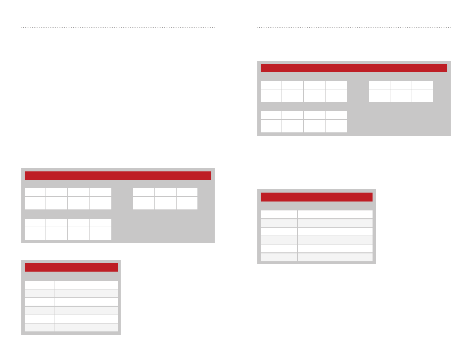
Maximum Transmit Retries - Address = 0x52; NV Address = 0x07
regMAXTXRETRY sets the number of transmission retries if an
acknowledgement is not received. If an acknowledgement is not received
after the last retry, EX_NORFACK is raised. Figure 38 shows examples of
the command.
The time between retries depends on the current baud rate. Figure 39
shows the time between retries based on baud rate. The retry number
times the timeout times gives the potential latency before a new message
can be sent.
Figure 38: 250 Series Maximum Transmit Retries Command and Response
250 Series Acknowledgement Timeout Times
Baud Rate
Timeout Time
2400
170ms
9600
75ms
19200
45ms
38400
30ms
57600
30ms
115200
30ms
Figure 39: 250 Series Acknowledgement Timeout Times
250 Series Maximum Transmit Retries
Read Command
Read Response
Header
Size
Escape
Address
ACK
Address
Value
0xFF
0x02
0xFE
0x52
0x07
0x06
0x52
0x07
V1
Write Command
Header
Size
Address
Value
0xFF
0x02
0x52
0x07
V1
Transmit Wait Timeout - Address = 0x50; NV Address = 0x05
When a byte is received from the UART, the module starts a timer that
counts down every millisecond. The timer is restarted when each byte is
received. The value for the regTXTO register is the number of milliseconds
to wait before transmitting the data in the UART receive buffer. The default
setting for this register is 0x10 (~16ms delay).
If the timer reaches zero before the next byte is received from the UART,
the module begins transmitting the data in the buffer. This timeout value
should be greater than one byte time at the current UART data rate with a
minimum of 0x02. It should not be set to a value of 0x01 or any value less
than one byte time as unpredictable results could occur.
If the timeout value is set to 0x00, the transmit wait timeout is deactivated.
In this case, the transceiver waits until a number of bytes equal to the
Minimum Transmission Unit (MTU) have been received by the UART. All
of the bytes are sent once the MTU has been reached. Figure 36 shows
examples of the commands. Figure 37 shows the minimum timeout values
based on baud rate.
Figure 36: 250 Series Transmit Wait Timeout Command and Response
250 Series Minimum TXTO Values
Baud Rate
Minimum TXTO
2,400
6ms
9,600
3ms
19,200
2ms
38,400
2ms
57,600
2ms
115,200
2ms
Figure 37: 250 Series Transmit Wait Timeout Minimum Values
250 Series Transmit Wait Timeout
Read Command
Read Response
Header
Size
Escape
Address
ACK
Address
Value
0xFF
0x02
0xFE
0x50
0x05
0x06
0x50
0x05
V1
Write Command
Header
Size
Address
Value
0xFF
0x02
0x50
0x05
V1