Writing to registers, Reading from registers, Configuration registers – Linx Technologies TRM-915-R250 User Manual
Page 20: Regcrcerrcount, Reghoptable, Regnvhoptable
– –
– –
34
35
Configuration Registers
The following sections give details on each configuration register. Green
addresses in the tables are volatile locations and blue are non-volatile.
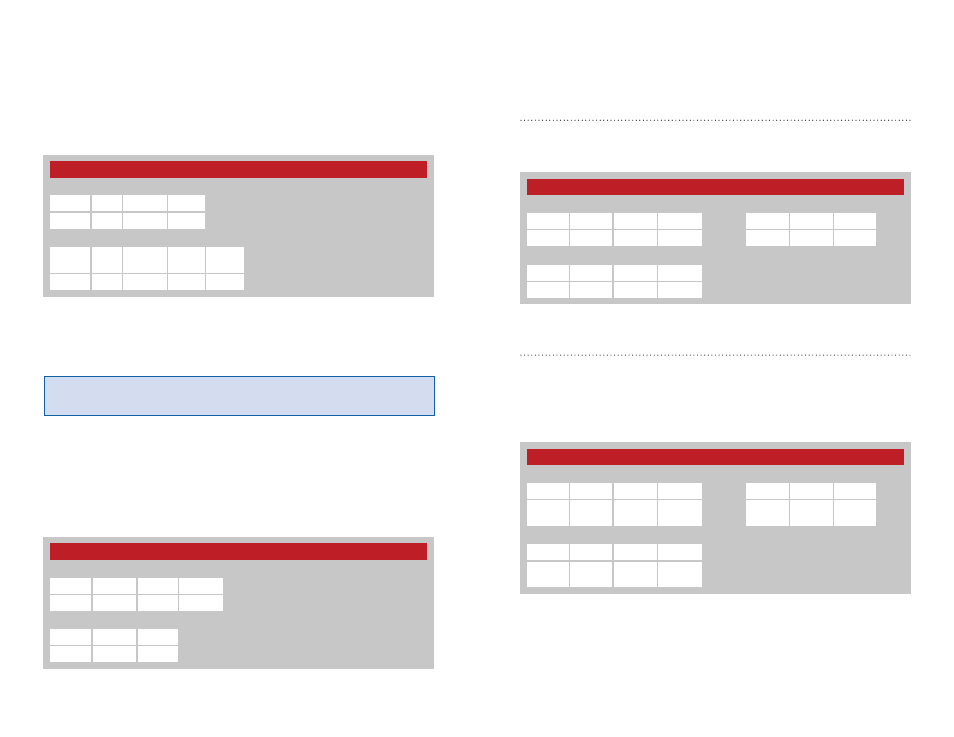
CRC Error Count - Address = 0x40
The value in the regCRCERRCOUNT register is incremented each time
a packet is received that fails CRC check. Writing 0x00 to this register
initializes the count. Figure 27 shows the command and response.
Channel Hop Table - Address = 0x4B; NV Address = 0x00
The module supports 6 different hop sequences with minimal correlation.
The sequence is set by the value in the regHOPTABLE register. Changing
the hop sequence changes the physical band utilization, much the same
way that a channel does in a static transmitter. Valid values are 0-5. Figure
28 shows the command and response.
Figure 29 shows the RF channels used by the 250 Series and the hop
sequences referenced by channel number. The default hop sequence is 0.
Figure 27: 250 Series CRC Error Count Command and Response
Figure 28: 250 Series Channel Hop Table Command and Response
250 Series CRC Error Count
Read Command
Read Response
Header
Size
Escape
Address
ACK
Address
Value
0xFF
0x02
0xFE
0x40
0x06
0x40
V1
Write Command
Header
Size
Address
Value
0xFF
0x02
0x40
V1
250 Series Channel Hop Table
Read Command
Read Response
Header
Size
Escape
Address
ACK
Address
Value
0xFF
0x02
0xFE
0x4B
0x00
0x06
0x4B
0x00
V1
Write Command
Header
Size
Address
Value
0xFF
0x02
0x4B
0x00
V1
Writing to Registers
Writing to a volatile register is nearly instantaneous. Writing to a non-volatile
register typically takes 16ms. Because the packet size can vary based on
the need for encoding, there are two possible packet structures. The first
structure writes a value that is less than 128 (0x80) and the second writes
a value that is higher. The higher value must be split into two values. Figure
25 shows the byte sequences for writing a register in each case.
The module responds with an ACK (0x06). If it is not received, the
command should be resent. The module responds with a NACK (0x15) if a
write is attempted to a read-only or invalid register.
Reading from Registers
A register read command is constructed by placing an escape character
(0xFE) before the register number. The module responds by sending an
ACK (0x06) followed by the register number and register value. The register
value is sent unmodified, so if the register value is 0x83, 0x83 is returned.
If the register number is invalid, the module responds with a NACK (0x15).
The command and response are shown in Figure 26.
Figure 26: 250 Series Read from Configuration Register Command and Response
Warning:
The module must remain powered for the duration of the
register write or important configuration information could be lost.
Figure 25: 250 Series Write to Configuration Register Command
250 Series Read From Configuration Register
Command
Header
Size
Escape Address
0xFF
0x02
0xFE
REG
Response
ACK
Address
Value
0x06
REG
V1
250 Series Write to Configuration Register Command
Command for a Value less than 128 (0x80)
Header
Size
Address
Value
0xFF
0x02
REG
V1
Command for a Value greater than 128 (0x80)
Header
Size
Address
Value
1
Value
2
0xFF
0x03
REG
0xFE
V2