Using the reset line – Linx Technologies TRM-915-R250 User Manual
Page 15
– –
– –
24
25
250 Series Transceiver Reset Circuit Specifications
Parameter
Min.
Typ.
Max. Units Notes
RESET Output Low Voltage
0.6
V
V
CC
= 2.7 – 3.6V
RESET Input Pull-up Current
25
40
µA
RESET = 0.0V
V
CC
Monitor Threshold (V
RST
)
2.40
2.55
2.70
V
Minimum RESET Low Time to
Generate a Hardware Reset
15
µs
Power-on Reset Delay (T
PORDelay
)
<300
µs
V
CC
Ramp Time is Valid
Allowed/Valid V
CC
Ramp Time
1
ms
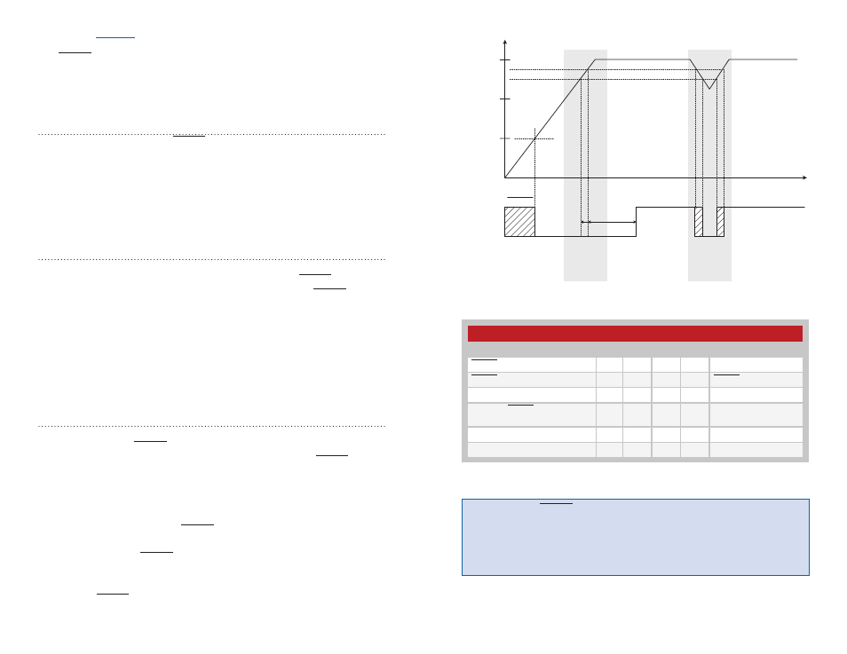
Power-On
Reset
VCC
Monitor
Reset
RESET
t
volt
s
1.0
2.0
Logic HIGH
Logic LOW
T
PORDelay
VCC
2.70
2.55
V
RST
VCC
Warning:
If the RESET line experiences noise, it can cause multiple
triggers (wake from sleep, hardware reset, hardware reset, etc.) and
cause the volatile registers to be reloaded with their non-volatile values. If
the circuit introduces noise onto this line, a bypass capacitor or RC filter
should be placed on the line as close to the module as is practical.
Figure 17: 250 Series Transceiver Reset Timing Diagram
Using the RESET Line
The RESET line has different functions depending on the state the module
is in. It is an open-drain input/output line with an integrated weak pull-up,
so it is normally high. Because it periodically operates as an output,
external control should only pull this line low, not high.
Hardware Reset (Input)
During normal operation, the RESET line functions as an active-low
hardware reset input. Taking this line low for at least 15µs forces the
module’s controller into hardware reset. While the line is low, execution of
module operations are suspended and all module lines revert to open-drain
inputs with weak pull-ups. This behavior can be exploited during power-up
if the V
CC
ramp time exceeds 1ms. By suspending execution, the dangers
associated with slow V
CC
ramp are eliminated.
Wake from Deep Sleep (Input)
When the module is in deep sleep, all execution is suspended in the
controller and the radio is in its lowest power mode. The RESET line must
be lowered for at least 15µs to wake the module. When the RESET line is
raised, execution begins in the controller. The module maintains its state
engine while asleep. Because of this, it can detect whether the hardware
reset was intended to cause a hard reset or wake the module. The
controller’s RAM is preserved during deep sleep. The RAM is checked prior
to entering deep sleep, and examined upon waking. If the RAM contents
are corrupted upon wake, the module issues itself a software reset to
reinitialize the module.
Hardware Reset Indicator (Output)
When the module starts from power-off, or is reset by the internal V
CC
monitor circuitry, the RESET line is driven low to indicate the reset state.
During power-on reset, assuming the V
CC
ramp time is valid, RESET is
driven low from the time that V
CC
reaches approximately 1V until V
CC
reaches V
RST
+ T
PORDelay
. T
PORDelay
is the power-on reset delay imposed by the
controller’s hardware.
The other event that drives the RESET line low is a low-voltage or
brown-out condition. In this case, the V
CC
monitor holds the module in
reset, thus driving the RESET line low. It remains low until the power drops
below the operating threshold for that circuit (becoming indeterminate),
or until the module’s power supply returns to V
RST
operation of RESET as an output.
Figure 18: 250 Series Transceiver Reset Circuit Specifications