Installation, Kvm switch installation – Rose Electronics Orion User Manual
Page 12
INSTALLATION
6
Orion Installation and Operations Manual
The installation section of this manual is divided into a section for the KVM Switch installation and for the Cross-Point
Switch installation procedures. Please turn to the section needed for your application.
KVM Switch Installation
As a KVM Switch the device supports several operation modes:
(See appendix F for cascading configuration example)
16 User ports and 32 CPU ports for Single-Head access
8 User ports and 16 CPU ports for Dual-Head access
4 User ports and 8 CPU ports for Quad-Head access.
Single, Dual, and Quad CPUs and User ports may also be operated in mixed mode.
The maximum number of User ports depends on the detailed configuration.
A maximum of 32 CPUs (up to 10 km away using fiber cable) can be connected to the
Unit via Local transmitter units installed at each CPU.
Up to 16 remote user stations (up to 10 km away using fiber cable) can be connected
to the Orion unit via remote receiver units installed at each console.
The installation of the local transmitter(s) and remote
receivers(s) will vary depending on the needed
application. (Single head, dual head, or quad head KVM
switch, serial and audio options, etc.)
Basic transmitter installation:
(Each connected computer must be connected to a KVM
transmitter and each remote KVM user station must be
connected to a KVM receiver)
1. Connect the DVI video connector(s) from the
computer to the transmitter using a DVI-I MM cable.
2. Connect a USB cable (Type A to Type B) from the
computer’s USB Type A connector to the
transmitters USB Type B connector.
3. If the transmitter has the serial and audio options,
connect these ports to the transmitter using
standard stereo audio cables (MM) for the speaker
and microphone connectors and a DB9 serial cable
from the computer to the transmitter.
4. Connect a CATx or Fiber cable (depending on the
model – up to 32 cables) from the transmitter’s port
to the corresponding CPU port on the Orion unit.
Basic receiver installation:
1. Connect the DVI-I video monitor’s cable to the
corresponding connector on the receiver
2. Connect the USB keyboard and USB mouse to the
keyboard and mouse USB ports on the receiver
3. If the receiver has the serial and audio options,
connect a speaker set to the speaker connector and
a microphone to the Mic input connector.
5. Connect a CATx or Fiber cable (depending on the
model – up to 16 cables) from the receiver’s port to
the corresponding CON port on the Orion unit.
NOTE: If you Orion unit has a mixture of CATx and Fiber
modules, care should be taken to only connect a CATx
connected user station to a CATx connected computer or
a Fiber connected user station to a fiber connected
computer.
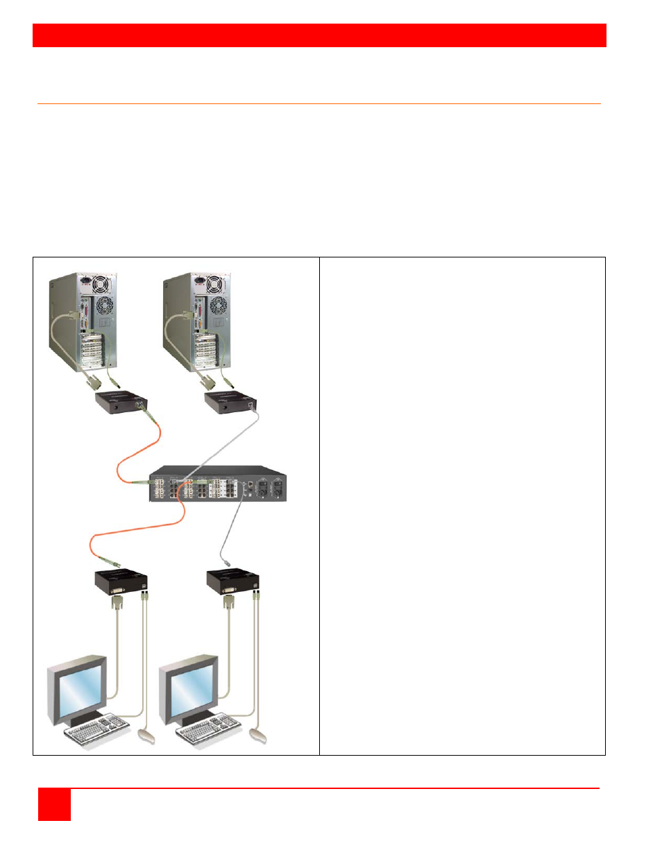
Figure 2. Typical KVM Switch Configuration
Transmitter(s)
up to 32
Receiver(s)
up to 16
Fiber
or
CATx
Fiber
or
CATx