Rose Electronics Orion User Manual
Page 49
Orion Installation and Operations Manual
43
Appendix C – DDC / Color depth set-up (Local Unit)
The DDC information and color depth can be modified from the default value settings (Obtain the DDC information
from the internal DDC table and 16/24Bit auto-select color depth). Refer to Appendix C for instructions on changing
the default values.
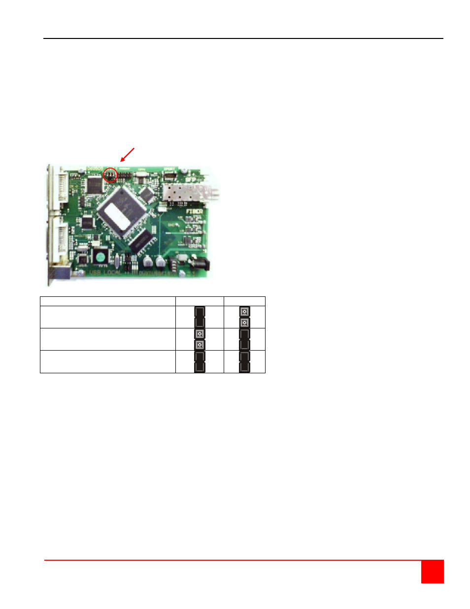
Remove the upper portion of the unit chassis and orient the PC board as shown below. Note the location of jumpers
JP1, JP2, and JP3 on the local unit (Transmitter).
JP1 and JP2 are used to select if the DDC information is taken from the internal DDC table, from the local monitor or
from the remote monitor. Set the jumpers as shown in table 1 for the selection required.
JP1, JP2, JP3
Location
DDC
JP1
JP2
From internal DDC table (Default)
From the local monitor
From the remote monitor ***
*** Procedure for loading the DDC information from the remote monitor:
Switch on the system: Local and Remote Unit, CPU and monitor. Connect the CPU with Local Unit and Remote
Unit with monitor (On Dual-Head devices, connect BOTH monitors). Connect Local and Remote Unit with the
CATx or fiber cable.
Unplug the remote monitor’s video-cable from the Remote Unit (On Dual-Head devices, unplug BOTH monitors).
Switch on the monitor if it is switched off. On Dual-Head devices, connect and switch on BOTH monitors!)
Re-plug the remote monitor’s video-cable into the Remote Unit (On Dual-Head devices, re-plug BOTH monitors).
The DDC information of the remote monitors is read automatically, transferred to the Local Unit and stored into
the DDC-EPROM.
After a successful reprogramming, the Video-OK’ LED at the Local Unit blinks rapidly for approx. 1 second.
JP1, JP2, JP3