Notice – Thermo Pride Air Handler MA User Manual
Page 21
5
AIR FILTERS
Air filters and filter racks must be field supplied.
.
SUSPENSION KITS
A suspension kit is available. Models 1BH0601 (unit size 018-060) is
designed specifically for the units contained in this instruction (upflow
application only). For installation of these accessory kits, see the
instructions packed with the kit.
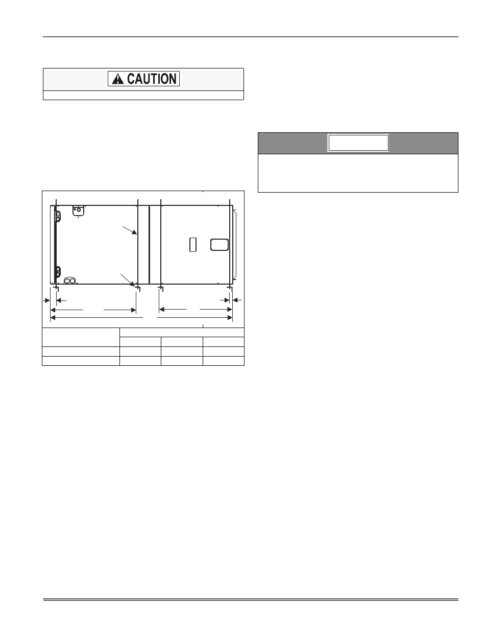
HORIZONTAL SUSPENSION
For suspension of these units in horizontal applications, it is recom-
mended to use angle steel support brackets with threaded rods, sup-
porting the units from the bottom, at the locations shown in Figure 4.
SECTION IV: ELECTRIC HEATER
INSTALLATION
If the air handler requires electric heat, install the electric heat kit
according to the installation instructions included with the kit. After
installing the kit, mark the air handler nameplate to designate the heater
kit that was installed. If no heater is installed, mark the name plate
appropriately to indicate that no heat kit is installed.
The HEAT ENABLE jumper (See Figure 5) must be moved to the HEAT
position to enable operation of the heater
Use only 4HK heater kits, as listed on Air Handler name plate and in
these Instructions. Use data from Tables 9 and 12 for information on
required minimum motor speed tap to be used for heating operation,
maximum over-current protection device required and minimum electri-
cal supply wiring size required for listed combination of Air Handler and
Heater Kit.
For Upflow, Downflow and Horizontal right hand applications the kits
can be installed without modification.
Field modification is required for Horizontal left-hand airflow application
only. Follow instructions with heater for modification.
SECTION V: LOW VOLTAGE CONTROL
CONNECTIONS
This air handler can be connected to the wall thermostat and outdoor A/
C or heat pump using either conventional low voltage (24 VAC) thermo-
stat wiring OR using four-wire digital communications wiring. To use
conventional low voltage wiring, see the section below entitled “Con-
ventional Low Voltage Control Wiring”. To use four-wire communica-
tions control wiring, see the section below entitled “Control Wiring using
Communicating Controls”.
The Communicating System consists of several intelligent communicat-
ing components including the Communicating Thermostat Control
(touch-screen wall thermostat), variable speed air handler, air condi-
tioner (15 and 18 SEER premium air conditioners) or heat pump (13, 15
and 18 SEER premium heat pumps), which continually communicate
with each other via a four-wire connection called the A-R-C-B. Com-
mands, operating conditions, and other data are passed continually
between components over the A-R-C-B bus. See Figure 8. The result is
a new level of comfort, versatility, and simplicity.
In order to use this air handler in full communications (COMM) mode, it
MUST be installed with the matching touch-screen Communicating
Control (wall thermostat) and an outdoor air conditioner or heat pump
with a fully communicating control.
This air handler may also be used along with the Communicating Ther-
mostat Control and a non-communicating outdoor air conditioner
through the addition of a communicating Outdoor Aux Control board to
the outdoor unit. This system allows full communication between the air
handler and thermostat and limited communication to the outdoor unit.
Equipment should never be operated without filters.
Units
(Nominal Tons)
Dimension
WW
XX
YY
1-1/2 - 3 Ton
16”
48”
22”
3-1/2 - 5 Ton
24”
53” - 58”
22”
FIGURE 5: Typical Horizontal Installation
WW
XX
SUSPENSION SUPPORT LOCATIONS FOR HORIZONTAL APPLICATIONS
2
1-1/2
MIN. 1-1/2” x 1-1/2” Angle
Recommended length
26” minimum
with 2” clearance on
both sides of Air Handler
MIN. 3/8”
THREADED ROD
YY
If a heat kit with a circuit breaker is installed in the air handler, the
circuit breaker cover cladding must be removed to gain access to
the sheet metal cover plate. Some local codes may require that the
circuit breaker remain visible. If so, do not re-install circuit breaker
cover cladding.
NOTICE