Thermo Pride Air Handler MA User Manual
Page 23
7
* Optional dehumidification humidistat switch contacts open on humidity rise.
NOTES:
1. “Y/Y2” Terminal on air handler control board must be connected for full CFM and applications requiring 60 second blower off delay for SEER enhancement.
2. Remove humidistat jumper on air handler control board.
3. For heat pump applications - set MODE jumper on air handler control board to the HP position.
4. To change quantity of heat during HP defrost cycle - reverse connections at W1 and W2 on air handler control board.
.
* Optional dehumidification humidistat switch contacts open on humidity rise.
NOTES:
1. “Y/Y2” Terminal on air handler control board must be connected for full CFM and applications requiring 60 second blower off delay for SEER enhancement.
2. Remove humidistat jumper on air handler control board.
3. For heat pump applications - set MODE jumper on air handler control board to the HP position.
4. To change quantity of heat during HP defrost cycle - reverse connections at W1 and W2 on air handler control board
CONTROL WIRING USING COMMUNICATING
CONTROLS
Use the wiring diagram below to connect the air handler control, Com-
municating Control (wall thermostat) and communicating outdoor unit.
Be sure that all of the “A” terminals are connected together, all of the “B”
terminals are connected together, all of the “C” terminals are connected
together and all of the “R” terminals are connected together. See Figure
8. When using a fully communicating system, the large screw terminals
(C, G, R, etc.) on the air handler control are not used. The four small
screw terminals in the terminal block on the end of the furnace control
should be used.
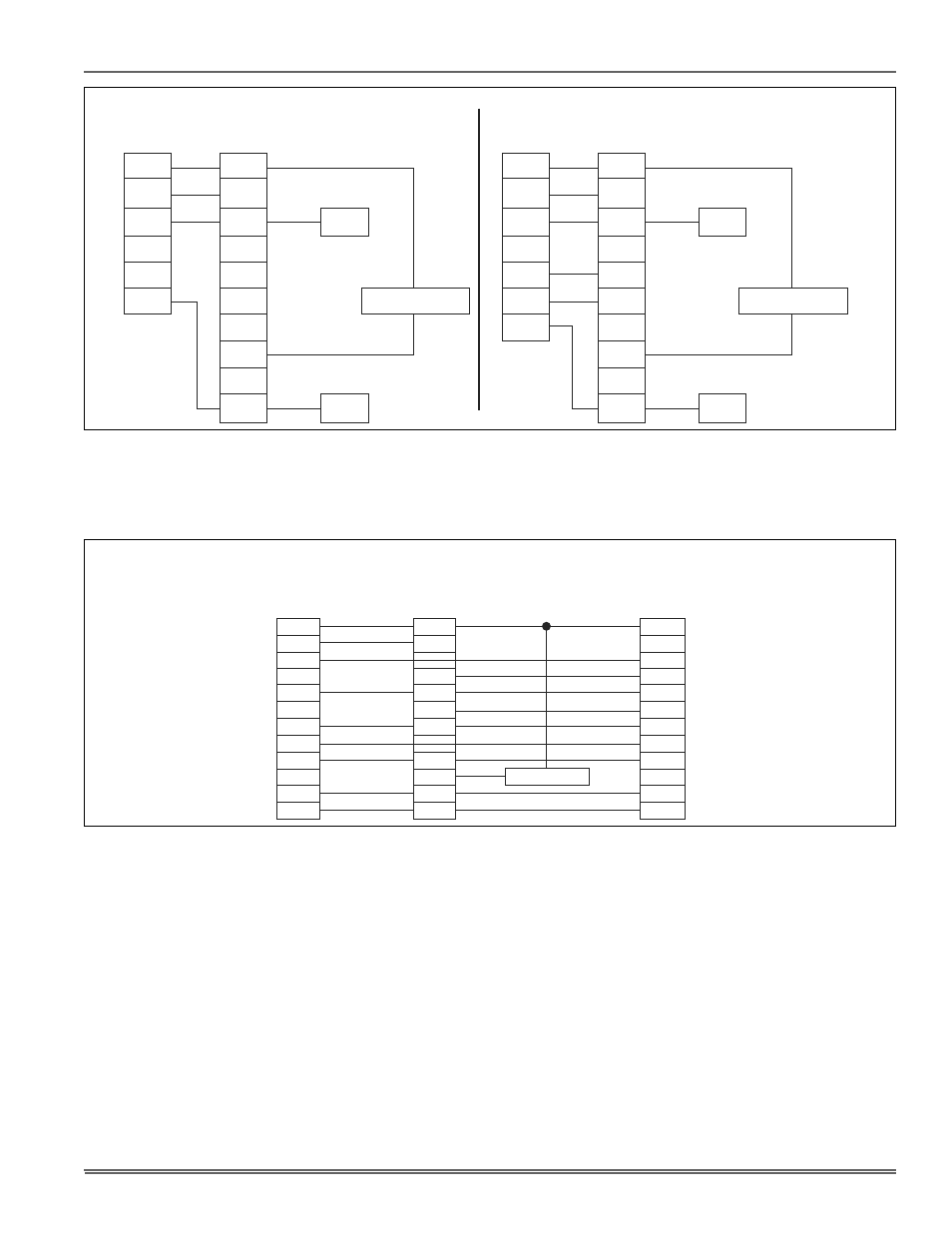
FIGURE 7: Cooling Models with and without Electric Heat Wiring
Air Handler Control Wiring
Typical A/C - Cooling only Applications
THERMOSTAT
AIR HANDLER
BOARD
1 - STAGE
AIR CONDITIONING
R
R
G
Y
W1
W2
C
G
W1
W2
Y
C
Y / Y2
Y1
O
HUM
X / L
COM
HUMIDISTAT *
THERMOSTAT
AIR HANDLER
BOARD
1 - STAGE
AIR CONDITIONING
R
R
G
Y
W1
W2
C
G
W1
W2
Y
C
Y / Y2
Y1
O
HUM
X / L
COM
HUMIDISTAT *
Air Handler Control Wiring
Typical A/C with Electric Heat Applications
FIGURE 8: Two-Stage Heat Pump Wiring
CONTROL WIRING - Air Handler & UPG HP Systems
Two Stage H/P with York Guard VI Board & Copeland “Ultra Tech”
Conventional Application - Not Hot Heat Pump
THERMOSTAT
AIR HANDLER
BOARD
2 - STAGE SCROLL
HEAT PUMP
R
R
R
G
G
Y2
E
W
W
O
O
O
X / L
X / L
X / L
C
C
Y / Y2
Y1
Y1
Y2 OUT
Y2
W2 OUT
W1 OUT
BS
W2
W1
HUM
COM
HUMIDISTAT *
Y1