Notice – Thermo Pride Air Handler MA User Manual
Page 26
10
SECTION VIII: AIRFLOW AND COMFORT
SETTING SELECTION
AIRFLOW SELECTION
The airflow and comfort setting selection jumpers must be set properly
at the time of installation for proper system operation. Place jumpers in
the proper locations based on the information shown in Table 15 and
Figure 5.
Inputs to air handler control board are passed to the motor which deter-
mines the target CFM to be delivered. The following inputs will produce
the CFM per the appropriate table and selected tap settings.
These variable speed air handlers are designed to deliver constant air-
flow (CFM) regardless of the external static pressure (ESP) in the duct-
work. Therefore, if too many supply registers are closed, a filter
becomes clogged, or there is a restriction in the ductwork, the motor will
automatically operate at a higher speed to compensate for the higher
ESP. This may result in a higher operating sound level.
To Set Cooling Airflow:
Refer to the outdoor unit technical guide for the recommended airflow
with the matching evaporator coil. Refer to Table 15 for the possible
high speed cooling and heat pump airflow selections.
Find the recommended system airflow in Table 15 for the installed air
handler model.
Select the COOL airflow you need from Table 15. Set the COOL and
ADJUST Jumpers on the control as indicated in Table 15.
To Set Heat Pump Airflow:
The heat pump airflow setting is the same as the cooling airflow setting.
No additional airflow setting is required. However, you must set the
MODE jumper to the HP position for proper system operation (See Fig-
ure 5).
To Set Electric W1 Heat Airflow:
The blower speed required for 1st stage electric heat is different than
cooling. Refer to Table 15 for the possible CFM selections. Refer to
Table 9 for the minimum required airflow for the electric heater installed.
Find the desired airflow in Table 15 for low heat. Set the HEAT jumper
on the control as indicated in Table 15.
To Set W2 Electric Heat Airflow:
Airflow for any W2 input, which is for Stages 2 & 3 of electric heat, is the
indicated CFM for high heat tap selection on Table 15.
Fan Only CFM:
When the connection is made from "R" to "G", the fan only mode is acti-
vated. In this mode, the airflow will depend on the position of the CONT
Fan jumper. In the “H” position, the blower will deliver 85-90% of full
capacity. In the “M” position, the blower will deliver 60-65% of full
capacity. In the “L” position, the blower will deliver 30-35% of full capac-
ity.
Blower Ramp-Up /Ramp-Down:
To minimize the sound made by the blower when it speeds up or slows
down, the blower will slowly ramp up or down from one speed to
another. Changes in blower speed during A/C or heat pump heating can
take up to 30 seconds. Changes in blower speed during electric strip
heating can take up to 15 seconds.
COMFORT SETTINGS
Normal
The normal setting provides a ramp-up from zero airflow to full capacity
and a ramp-down from full capacity back to zero airflow.
Humid
The humid setting is best-suited for installations where the humidity is
frequently very high during cooling season, such as in the southern part
of the country. On a call for cooling, t
he blower will ramp up to 50% of full capacity and will stay there for two
minutes, then will ramp up to 82% of full capacity and will stay there for
five minutes, and then will ramp up to full capacity, where it will stay until
the wall thermostat is satisfied.
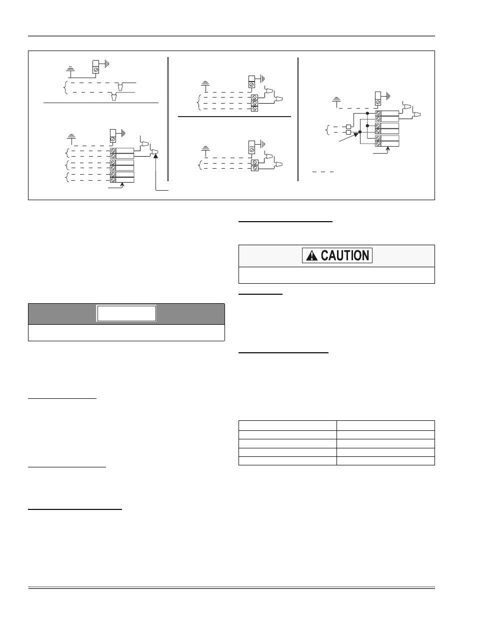
FIGURE 10: Line Power Connections
ELECTRIC HEAT
WITHOUT CIRCUIT BREAKER
SINGLE SOURCE (2.5 - 10 KW)
GND. LUG
POWER
SUPPLY
GND.
LUG
ELECTRIC HEAT
WITHOUT CIRCUIT BREAKER
3 PHASE (10 - 15 KW)
GND. LUG
POWER
SUPPLY
GND.
LUG
1 PHASE ELECTRIC HEAT
WITH CIRCUIT BREAKER
AS SHIPPED FROM FACTORY
SINGLE SOURCE
(2.5 - 25 KW) - 25 KW SHOWN
GND. LUG
POWER
SUPPLY
GND.
LUG
1 PHASE ELECTRIC HEAT
WITH CIRCUIT BREAKER
& BREAKER BAR REMOVED
MULTI-SOURCE (15 - 25 KW) - 25 KW SHOWN
GND. LUG
POWER
SUPPLY 1
GND.
LUG
POWER
SUPPLY 2
POWER
SUPPLY 3
TYPICAL WIRING WITHOUT ELECTRIC HEAT
GND. LUG
POWER
SUPPLY
GND.
LUG
POWER WIRING (208/230-1-60)
NOTE: USE ONLY COPPER CONDUCTORS
TERMINAL
BLOCK
TERMINAL
BLOCK
MAY BE 1, 2, OR 3
CIRCUIT BREAKERS
MAY BE 1, 2, OR 3
CIRCUIT BREAKERS
(JUMPER BAR)
CONNECT TRANSFORMER LEADS WITH WIRE NUTS
(TYPICAL ALL HEAT KITS)
Incorrect airflow and comfort settings may result in decreased sys-
tem efficiency and performance.
NOTICE
DO NOT change the ADJUST tap position on the control as this will
change your cooling airflow previously selected.
TABLE 5: Comfort Setting Selection
DELAY TAP
COMFORT SETTING
A
Normal
B
Humid
C
Dry
D
Temperate