Tcd600 isolated outputs – Nexen TCD600E 912145 User Manual
Page 10
FORM NO. L-20348-F-0705
10
TCD600 ISOLATED OUTPUTS
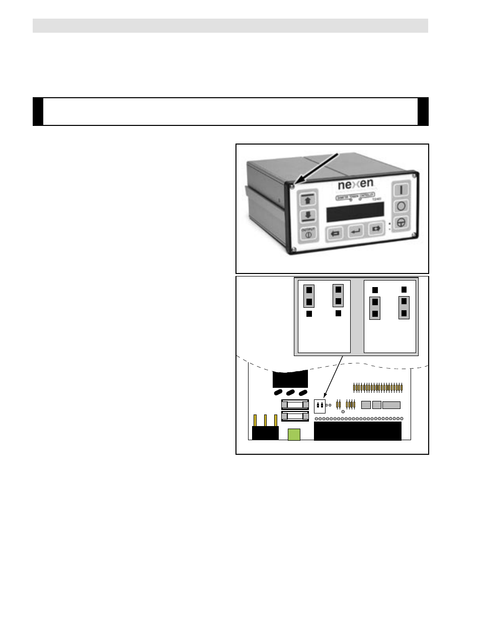
Changing the Output Isolation Setting
1.
Disconnect all electrical power from the TCD600.
2.
Remove all terminal block plug connectors from the
back of the TCD600.
3.
Remove six fasteners from the back nomenclature
panel.
4.
Remove the upper left hand fastener from the front
membrane switch panel. (See figure 10C)
5.
Pull the top panel of the enclosure toward the back
until it is completely removed.
6.
Locate JP1 and JP2 on the printed circuit board.
7.
Set the jumpers for the desired setting.
(See figure 10D.)
8.
Replace the top cover, back nomenclature panel and
all fasteners.
9.
Plug the connectors back into the terminal blocks.
10. Connect the 15 VDC power supply to terminal block
terminals 1 and 2.
(Terminal 1: +15 VDC Terminal 2: DC common)
11. Reconnect electrical power to the TCD600.
FIGURE 10C
JP1 JP2
JP1
JP2
Non-Isolated
Outputs
JP1
JP2
Isolated
Outputs
FIGURE 10D
The 0 -10 VDC and 4 - 20 mA tension control outputs can be isolated from the TCD600's power supply. This is often
done when connecting the outputs to a motor drive system or whenever there is a concern about ground loops caus-
ing electrical noise problems. A 15 VDC power supply is required and connects to terminal block positions 1 and 2,
see figure 10A. The TCD600 is shipped in the non-isolated setting. Two internal jumpers, JP1 and JP2, must be set
before the control outputs can be isolated. Refer to the following procedure to change the setting.
Note: Only the tension control outputs can be isolated. The diameter output signal can
not be isolated from within the TCD600.