Warning, 115v – Nexen TCD600E 912145 User Manual
Page 7
FORM NO. L-20348-F-0705
7
CAUTION
Observe polarity when connecting any devices
marked + and -.
Refer to Figure 10A and 10B for all electrical connec-
tions.
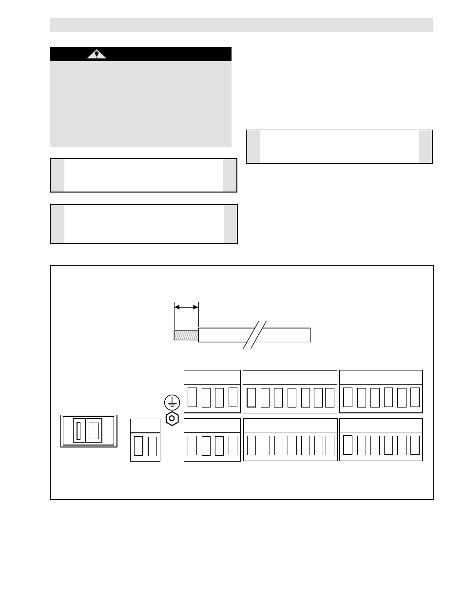
All wires to be inserted into the modular connectors must
be prepared ahead of time by stripping the insulation
1/4" from the end of the wire (See Figure 9). Twist the
end of each wire to be sure there are no loose or frayed
strands. Unplugging the modular connectors will make
wiring easier.
ELECTRICAL CONNECTIONS
STRIP INSULATION 1/4" BACK FROM END OF WIRE
After making all the connections, double-check each one
for accuracy and clamping tightness.
Apply AC power.
1/4"
FIGURE 9 - BACK PANEL ELECTRICAL CONNECTIONS
CAUTION
Wires must be stripped to the proper length to
avoid electrical shorting.
AC Select Switch
CAUTION
Make sure the AC Select Switch is in the proper
position, or damage could result to the TCD 600
(See Figure 9).
(continued...)
115/230 VAC
60/50Hz
30VA Max
L1 L2
1 2 3 4
18 19 20 21
5 6 7 8 9 10 11
22 23 24 25 26 27 28
12 13 14 15 16 17
29 30 31 32 33 3
4
115V
WARNING
Before connecting any wires, be sure that AC
power is turned off, locked and proper signage
applied according to safety regulations. All
wiring must be shielded or run through
conduit. Wire runs are to be no more than 300
feet. Connect all wires to the terminal strip on
the back panel of the TCD 600 (See Figure 9).
Avoid splicing wires.