Nexen TCD600E 912145 User Manual
Page 8
FORM NO. L-20348-F-0705
8
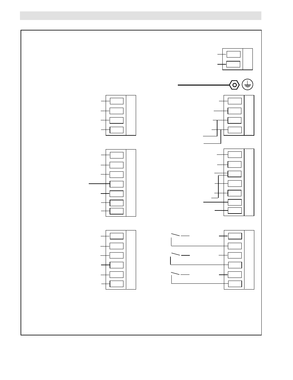
FIGURE 10A
ELECTRICAL CONNECTIONS
(TCD 600 Back Panel)
ELECTRICAL CONNECTIONS (continued...)
(continued...)
5
6
7
8
9
10
11
12
13
14
15
16
17
29
30
31
32
33
34
1
2
3
4
18
19
20
21
22
23
24
25
26
27
28
Not Used
Not Used
Not Used
Not Used
0 - 10 VDC
Control
Output
+
-
Shield
+ Minimum Diameter Alarm
- Minimum Diameter Alarm
+ Maximum Diameter Alarm
- Maximum Diameter Alarm
Remote
Hold/ Resume
Remote Start
Remote Stop
+
-
0 - 5 VDC
Roll Diameter
Output
Shield
Red, +15 VDC
Blac k, Common
Brown, Signal
To
Nexen
Encoder
{
o
o
o
o
o
o
{
115/230 VAC
Neutral/230 VAC
L1
L2
Not Used
Red, +24 VDC
Brown, +15 VDC
Blue, Com
Blac k, Signal
White, Signal
Blac k, Com
Shield
{
To
Pro ximity
Sensor
{
To
Ultrasonic
Sensor
To Ultrasonic
Sensor
{
Earth Ground
Com
+15 VDC
+
-
4-20 mA DC
Control Output
Blac k
Red
{
To EN40 or EN50
External Power Supply
Input for Isolated Control
Output Signals
{
Note 1.
Notes: 1. See Alarm Output Connection Diagrams on page 6.
{
{
.
.
See
See
Note 2.
2. Remote contact closures are momentary only.
3. Shield all signal wiring and keep away from wires carying
heavy loads or AC supply power.