Installation (continued...) – Nexen TCD600E 912145 User Manual
Page 6
FORM NO. L-20348-F-0705
6
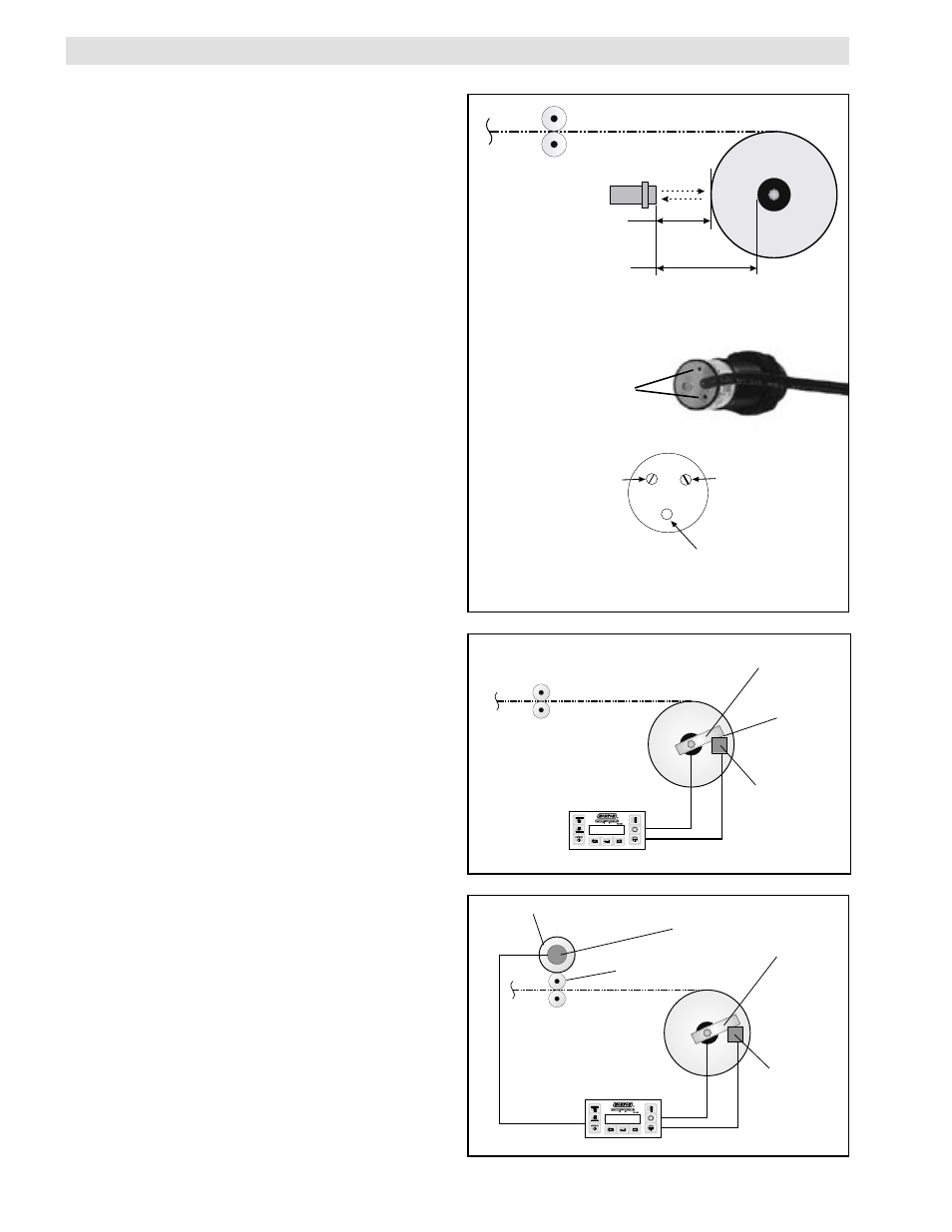
An Ultrasonic Sensor can measure the change in roll radius
by bouncing soundwaves off the material, enabling the
TCD 600 to calculate roll diameter. For calibrations to be
accurate, the sensor must be installed perpendicular to
the axis of the wind or unwind shaft. Also, the Ultrasonic
Sensor must be mounted at least four inches [100mm]
away from the maximum diameter roll.
A
DJUSTMENT
OF
THE
U
LTRASONIC
S
ENSOR
Nexen's Ultrasonic Sensor is factory adjusted for a 4 to 40
inch range and typically does not require re-adjustment prior
to use. If a shorter range is desired, then re-adjustment may
be performed by connecting a voltmeter to the sensor's
output and turning P1 for the near point adjustment and P2
for the far point adjustment. (See figure 6) Adjust P1 and
P2 until the output voltage covers as much of the 0 to 10
VDC range as possible over the desired distance.
NOTE: The indicator on the end of an Ultrasonic Sensor
shows an indication of signal strength. The indicator
will light GREEN when a target is out of range, and
fades to RED as a target moves into range, depend-
ing on how much reflected signal it receives from a
target.
A Proximity Switch (See Figure 7) is designed to count
revolutions as the roll turns by sensing an iron or steel
target once every revolution. Mount the Proximity Switch
to a secure, nonrotating member and set the gap between
the Nexen Proximity Switch and the target to .20 to .40
inch (5.1 - 10.3mm).
The target must be large enough to trigger the switch and
can be mounted to the roll shaft or any other mechanical
component that rotates at the same speed as the roll.
When using an Optical Encoder along with a Proximity
Switch (See Figure 8), precise diameter measurement of
the roll can be achieved.
The Optical Encoder is coupled to a measuring wheel
which, when rotated one full turn, equals 12 inches. The
Optical Encoder translates this rotation into 100 pulses per
foot. As a result, the Optical Encoder must be mounted
so as to ensure that the measuring wheel rotates at the
same speed as the web moving through the machine. A
good mounting location would have the measuring wheel
making contact with one of a pair of nip rollers, because
the pressure between these rollers ensures that there
will be no slippage between the web surface and the roll
surface. However, the wheel should NOT make direct
contact with the web as that might scratch or mar the
surface of the web.
FIGURE 6 - Ultrasonic Sensor
FIGURE 7
FIGURE 8
PROXIMITY
SWITCH
TARGET
PROXIMITY
SWITCH
TARGET
OPTICAL
ENCODER
GAP
NIP ROLLER
MEASURING WHEEL
ADJUSTING
SCREWS
SENSOR MOUNTING
INSTALLATION (continued...)
Ultrasonic Sensor
4" [100mm]
Minimum
40" [1,000mm]
Maximum
Green-Red
Indicator
P2
P1
(Near Point
Adjustment)
(Far Point
Adjustment)