Clock tabs –32 registers –32 frequency –32, Clock tabs, Registers – Altera Stratix IV GT 100G User Manual
Page 54: Frequency
6–32
Chapter 6: Board Test System
The Clock Control
Stratix IV GT 100G Development Kit User Guide
October 2010
Altera Corporation
The Clock Control communicates with the MAX II device on the board through the
JTAG bus. The Si5338 programmable oscillator is connected to the MAX II device
through a 2-wire serial bus.
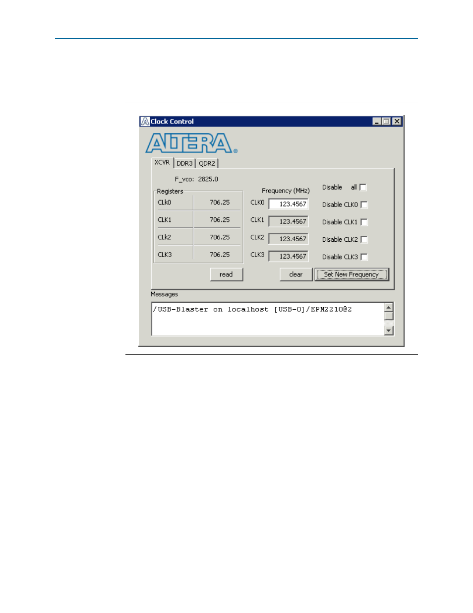
Figure 6–15
shows the Clock Control application.
The following sections describe the Clock Control controls.
Clock Tabs
There are three tabs to control each clock generator device. The XCVR tab controls the
clocks to the transceiver reference clock input. The default is 706.25 MHz. The DDR3
tab controls the clocks for the DDR3 interface. Its default along with the QDR2 tab is
100 MHz. The QDR2 tab controls the clocks for the QDRII interface.
Registers
The Registers control shows the current values from the clock driver.
Frequency
Enter the desired frequencies for each CLK. The range of this GUI is from 5 MHz to
710 MHz. There are some limitations for what frequencies are allowed.
f
For more information about the Si5338, refer to the datasheet on the Silicon Labs
website
(www.silabs.com)
.
Figure 6–15. The Clock Control