Connecting input signals, Connector pin diagram, Connection examples: step & dir – Applied Motion STR2 User Manual
Page 14: Internal circuit diagram, 14 str2 hardware manual, Step dir en out
14
STR2 Hardware Manual
920-0059B
1/30/2014
Connecting Input Signals
The STR drives have three inputs:
• STEP: a high speed digital input for step pulse commands, 5-24 volt logic
• DIR: a high speed digital input for the direction signal, 5-24 volt logic
• EN: a 5-24V input for commanding the removal of power from the motor, EN input must be
open 50 milliseconds before pulses are received.
Note: STEP and DIR inputs can be converted to STEP CW and STEP CCW by moving the inter-
nal jumper. See “Step 6: Step Pulse Type”.
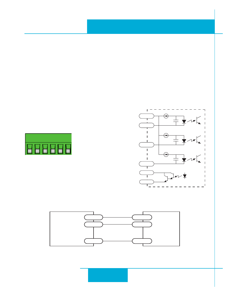
Connector Pin Diagram
Internal Circuit Diagram
STEP
DIR EN
OUT
+
OUT
–
COM+
inside drive
220 pF
COM+
STEP
220 pF
DIR
220 pF
EN
OUT+
OUT-
Connecting to Indexer with Sinking Outputs
STR2
+V OUT
COM+
DIR
DIR
STEP
STEP
Indexer
with
Sinking
Outputs
Connection Examples: STEP & DIR
See “System Wiring Recommendations” for cable instructions