Inputs and outputs (-s, -q, -ip), 22 swm24 hardware manual – Applied Motion SWM24IP-3EE User Manual
Page 22
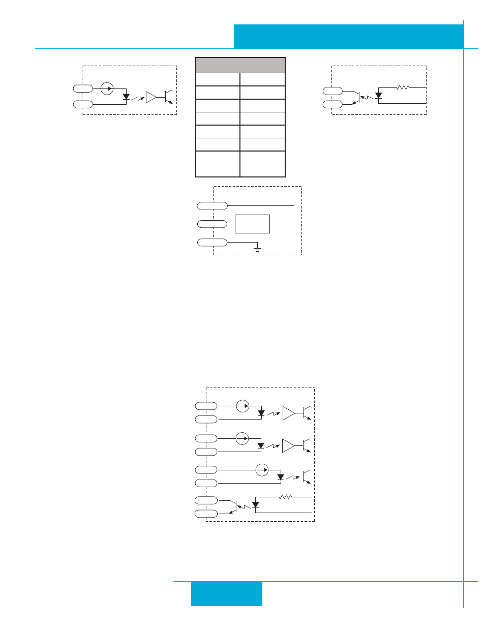
Equivalent Circuit: Analog Input (page 35 for details)
Inputs and Outputs (-S, -Q, -IP)
The SWM24S, SWM24Q, and SWM24IP have have three digital inputs and one digital output. IN1 and IN2 are high
speed inputs that can be configured for a number of different functions. Typically these inputs connect to an external
controller that provides step & direction command signals. You can also connect a master encoder to the high-speed
inputs for “following” applications. IN3 may be configured as an Enable/Disable input or a general purpose input. All 3
inputs can be configured in ST Configurator for use with Wait Input, If Input, Feed to Sensor, Seek Home and other SCL
or Q commands. The output (OUT) can be configured for different functions also. See table below. Example connec-
tion diagrams can be found on the following pages.
Equivalent Circuit (page 35 for details)
inside SWM24IP
IN1+
IN1-
IN2+
IN2-
IN3+
IN3-
OUT+
OUT-
PIN 1
PIN 3
PIN 5
PIN 8
PIN 12
PIN 11
PIN 4
PIN 6
inside drive
I/O-
I/O+
I/O Connector
inside drive
I/O-
I/O+
I/O Connector
inside drive
AIN
GND
Signal
Conditioning
+5V
50 mA max
PIN 10
PIN 9
PIN 7
I/O PIN
1+
1
1-
3
2+
5
2-
8
3+
6
3-
4
4+
11
4-
12
Equivalent Circuit: Flex I/O Point
Set as Input
Equivalent Circuit: Flex I/O Point
Set as Output
22
SWM24 Hardware Manual
920-0068B
10/31/2013