Connecting step and direction signals, 23 swm24 hardware manual – Applied Motion SWM24IP-3EE User Manual
Page 23
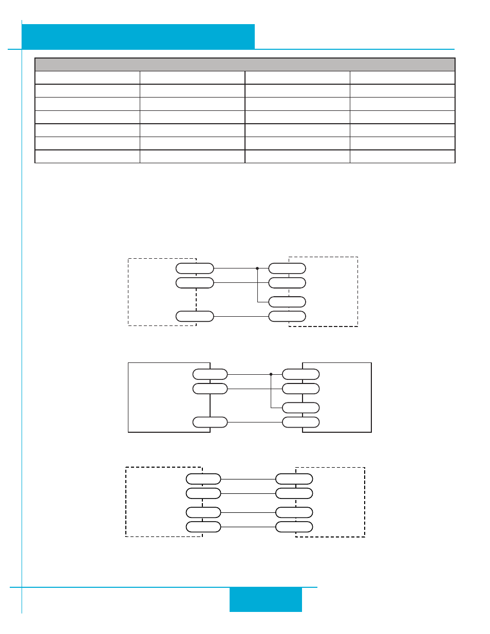
Connecting Step and Direction Signals
All SWM24 drives include two high-speed inputs that can accept 5 to 24 volt single-ended or differential signals, up to
3 MHz. These inputs can be connected to an external controller that provides step & direction (or step CW and step
CCW) command signals. You can also connect a master encoder to the high-speed inputs for “following” applications. Or
you can use these inputs with Wait Input, If Input, Feed to Sensor, Seek Home and other SCL or Q commands.
Connection diagrams follow.
Connecting to indexer with Sinking Outputs
Connecting to indexer with Sourcing Outputs
Connecting to Indexer with Differential Outputs
SWM24
I/O 2+
DIR
I/O 2-
I/O 1+
STEP
I/O 1-
Indexer
with
Sinking
Outputs
5-24 VDC
SWM24
COM
I/O 2-
DIR
I/O 2+
I/O 1-
STEP
I/O 2+
Indexer
with
Sourcing
O utputs
SWM24
Indexer
with
Differential
Outputs
DIR+
I/O 2+
DIR-
I/O 2-
I/O 1+
STEP-
STEP+
I/O 1-
I/O Functions (configure in software)
IN1
IN2
IN3
OUT
Clockwise Limit
Counterclockwise Limit Home Sensor
Fault
General Purpose Input
General Purpose Input
Enable Input
Brake
Step Input
Direction Input
General Purpose Input
Motion
Jog CW Input
Jog CCW Input
Tach
Enable Input
Alarm Reset Input
General Purpose Output
Start/Stop Input
23
SWM24 Hardware Manual
920-0068B
10/31/2013