Programmable output, 26 swm24 hardware manual – Applied Motion SWM24IP-3EE User Manual
Page 26
Programmable Output
The SWM24SF and SWM24QF include four “flex I/O” points which can be individually configured to act as digital out-
puts. The SWM24Q, SWM24S and SWM24IP includes one dedicated digital output. Each output can be set to auto-
matically control a motor brake, to signal a fault condition, to indicate when the motor is moving or to provide an output
frequency proportional to motor speed (tach signal). An output can also be turned on and off by program instructions
like Set Output. An output can be used to drive LEDs, relays and the inputs of other electronic devices like PLCs and
counters. The “OUT+” (collector) and “OUT-” (emitter) terminals of the transistor are available at the connector. This al-
lows you to configure the output for current sourcing or sinking.
Diagrams of various connection types follow.
Do not connect the output to more than 30VDC.
The current through the output terminal must not exceed 40ma.
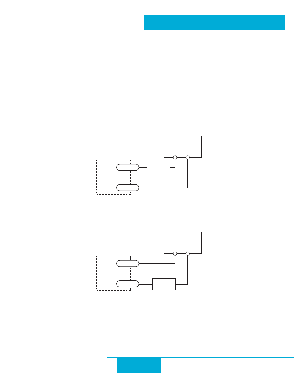
Connecting a Sinking Output
Connecting a Sourcing Output
5-24 VDC
Power Supply
+
–
Load
SWM24
OUT+
OUT-
5-24 VDC
Power Supply
+
–
Load
SWM24
OUT+
OUT-
26
SWM24 Hardware Manual
920-0068B
10/31/2013