Block diagram (-s, -q and -ip), 5swm24 hardware manual – Applied Motion SWM24IP-3EE User Manual
Page 5
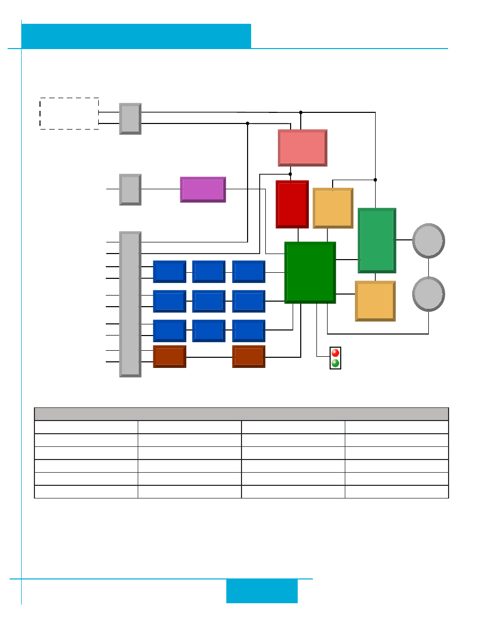
Block Diagram (-S, -Q and -IP)
12-70 VDC
External
Power Supply
Voltage &
Temp
Monitor
motor
encoder
encoder
5 Volt DC
Power Supply
DSP
Driver
Controller
3.3VDC
Logic
Supply
+
IN1+
Status
IN1-
IN2+
IN2-
IN3+
IN3-
OUT+
OUT-
GND
GND
+5VDC
+5V
-
Power Conn
I/O Connector
Ethernet
Network
COMM Conn
Ethernet
MAC/PHY
Digital
Filter
Optical
Isolation
Software
Filter
Digital
Filter
Optical
Isolation
Software
Filter
Digital
Filter
Optical
Isolation
Software
Filter
Optical
Isolation
Software
Filter
Over-
Current
Monitor
MOSFET
PWM
Power
Amplifier
I/O Functions (configure in software)
IN1
IN2
IN3
OUT
Clockwise Limit
Counterclockwise Limit Home Sensor
Fault
General Purpose Input
General Purpose Input
Enable Input
Brake
Master Encoder Ch.A
Master Encoder Ch.B
General Purpose Input
Motion
Tach
General Purpose Output
5
SWM24 Hardware Manual
920-0068B
10/31/2013