High speed digital inputs – Applied Motion BLuDC4-Q User Manual
Page 15
15
15
15
15
15
BLuDC-S,-Q Hardware manual
BLuDC-S,-Q Hardware manual
BLuDC-S,-Q Hardware manual
BLuDC-S,-Q Hardware manual
BLuDC-S,-Q Hardware manual
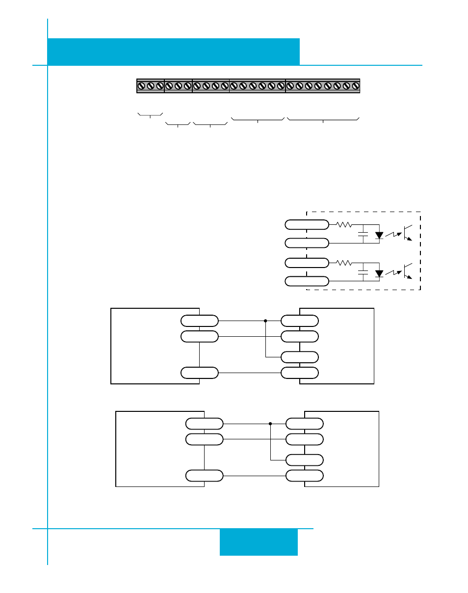
Connecting to indexer with Sourcing Outputs
BLU
Servo
Drive
COM
DIR-
DIR
DIR+
STEP-
STEP
STEP+
Indexer
with
Sourcing
Outputs
Connecting to Indexer with Sinking Outputs
(includes Applied Motion Si-1 Indexer)
BLU
Servo
Drive
+5V OUT
DIR+
DIR
DIR-
STEP+
STEP
STEP-
Indexer
with
Sinking
Outputs
OUT1+
OUT1-
OUT2+
OUT2-
OUT3+
OUT3-
OUT4+
OUT4-
IN1
COM
IN2
IN3
COM
IN4
IN7+
IN7-
IN8+
IN8-
IN5
COM
IN6
+5V
AIN
GND
Outputs
Single Ended
Inputs
Differential
Inputs
Single Ended
Inputs
Analog
Input
Expansion Input/Output Connector
BLU-SE and -QE only
High Speed Digital Inputs
The BLU-S and BLU-Q drives include two high speed inputs called STEP and DIR. They accept 5
volt single-ended or differential signals, up to 2 MHz.
Normally these inputs connect to an external controller that
provides step & direction command signals. You can also
connect a master encoder to the high speed inputs for
following applications.
Connection diagrams follow.
inside BLU Servo
330
220 pF
STEP/PWM+
STEP/PWM-
330
220 pF
DIRECTION+
DIRECTION-
12
11
10
9