4 s/c mounting plate assem, 5 belt tensioner/belt inst, S/c mounting plate assembly installation -3 – Paxton Superchargers Ford V-10 Super Duty Truck User Manual
Page 15
2-3
P/N: 4809606
©2005 Paxton Automotive
All Rights Reserved, Intl. Copr. Secured
06SEP05 v4.0 FordV10(4809606v4.0)
A.
Slide the three black aluminum spacers, about
1/2" thick, over the three studs protruding from
the front of the driver’s side head.
B.
Slide the supercharger mounting bracket over
the studs and spacers and attach with the sup-
plied three nuts and one bolt.(Appendix “C”.)
Hand tighten only at this time.
C.
Slide the mounting block between the super-
charger side-brace and the cylinder head.
Secure with the supplied 14mm x 2 x 50mm
long bolts, inserting through the side support
bracket through the mounting block and direct-
ly into the cylinder head. Tighten all of the fas-
teners that were left finger tight in Step “B”.
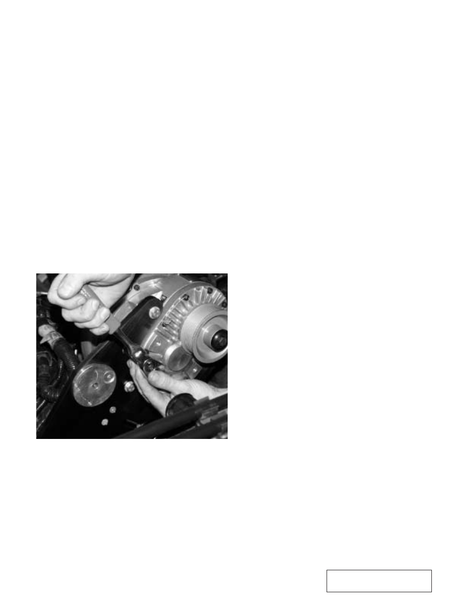
D.
Bolt the supercharger to the mounting bracket
using the six 3/8-16 x 2.0" bolts and washers
provided. (See Fig. 2.4-a.)
E.
Attach the oil feed line, installed during an ear-
lier step, to the 1/4"NPT x -4 x 90°NPT fitting
installed in the supercharger.
Fig 2.4-a
A.
Install the spring loaded tensioner and tensioner
mounting plate to the front cover of the super-
charger using two countersunk allen head bolts
and one 3/8-16 x 2.75"L bolt. (See Appendix
“E”.)
B
Install the supercharger belt by looping the belt
around the crank pulley, and then around the
supercharger pulley. You will need to rotate the
tensioner out of the way to do this. The belt
must be positioned so it is against the face of
the two idler pulleys. The belt will be twisted
sideways when it goes over the front of the
idlers. Next, with the tensioner rotated out of
the way, slip the belt under the grooved idler
then under the smooth idler.(See Appendix
“D”.)
2.5
BELT TENSIONER/BELT INSTAL-
LATION
2.4
S/C MOUNTING PLATE ASSEMBLY
INSTALLATION