Fuel pump installation, 1 fuel pump installation, 2 fuel pump relay – Paxton Superchargers Ford V-10 Super Duty Truck User Manual
Page 23: 3 fuel control unit instal, 4 fuel control unit vacuum, Fuel pump installation -1, Fuel pump relay -1, Fuel control unit installation -1, Fuel control unit vacuum line -1
6-1
P/N: 4809606
©2005 Paxton Automotive
All Rights Reserved, Intl. Copr. Secured
06SEP05 v4.0 FordV10(4809606v4.0)
Fig 6.1-a
*** NOTE ***
Depressurize the fuel system by removing the cap
on the schraeder valve and depressing the valve
using a pen or small screwdriver to release fuel
pressure. Cover the valve with a rag while this is
being done to prevent fuel spray.
A.
Locate the fuel filter inside the driver’s side
frame rail. Using the appropriate size fuel dis-
connect tool, disconnect the fuel line on the
output side of the fuel filter. Connect the fuel
pump inlet line to the disconnected port on the
fuel filter and the fuel pump outlet line to the
disconnected line going to the engine. (See Fig
6.1-a.)
*** NOTE ***
Hoses are left intentionally long so you have the
freedom in mounting.
B.
Trim lines as necessary. Route all fuel lines
away from any heat source or moving parts and
secure using supplied clamps and wire ties.
A.
Mount the relay in a safe, dry place in the
engine compartment away from any heat
source. Wire the relay as per Appendix “I”. On
terminal 86, tap in the pink with black stripe
wire that is located in the wiring harness
labeled “FS”going to the fuel pump.
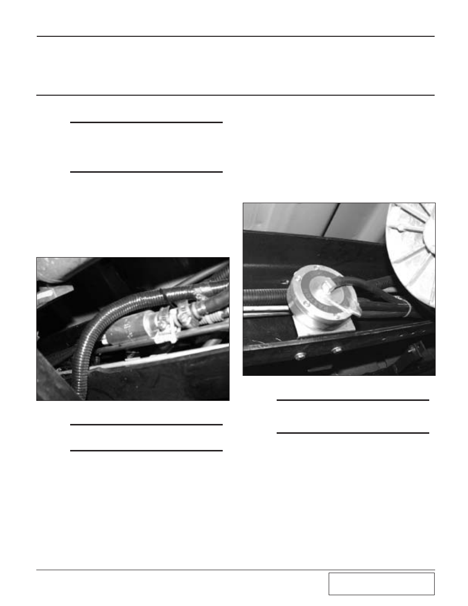
A.
Locate the fuel return line quick connect in the
frame rail on the driver’s side. Disconnect the
line and install the fuel control unit as per
Appendix “H”. Route all fuel lines away from
any heat source or moving parts and secure
using supplied wire-ties. Drill two 5/16" holes
in frame and mount the FCU using supplied
hardware. (See Fig 6.3-a.)
Section 6
FUEL PUMP INSTALLATION
Fig 6.3-a
*** NOTE ***
Some vehicles already have holes on the bottom
side of the frame rail that line up with the FCU
mounting holes.
6.4
FUEL CONTROL UNIT VACUUM
LINE
A.
Next, run the supplied vacuum line up to the
engine compartment. On vehicles with vacuum
boosted brakes, cut the vacuum line going to
the brake booster and install the supplied vacu-
um TEE, connect the FCU vacuum line to the
TEE. On vehicles with Hydro-Boost brakes,
route the FCU vacuum line to the capped port
on the passenger side of the Intake manifold
next to the throttle body.
6.3
FUEL CONTROL UNIT INSTAL-
LATION
6.2
FUEL PUMP RELAY
6.1
FUEL PUMP INSTALLATION