Supercharger air inlet as, 1 supercharger inlet duct, 2 air filter enclosure ins – Paxton Superchargers Ford V-10 Super Duty Truck User Manual
Page 19: Supercharger air inlet assembly installation, Supercharger inlet duct -1, Air filter enclosure installation -1, Supercharger air inlet tube
4-1
P/N: 4809606
©2005 Paxton Automotive
All Rights Reserved, Intl. Copr. Secured
06SEP05 v4.0 FordV10(4809606v4.0)
Fig 4.1-a
Fig 4.2-a
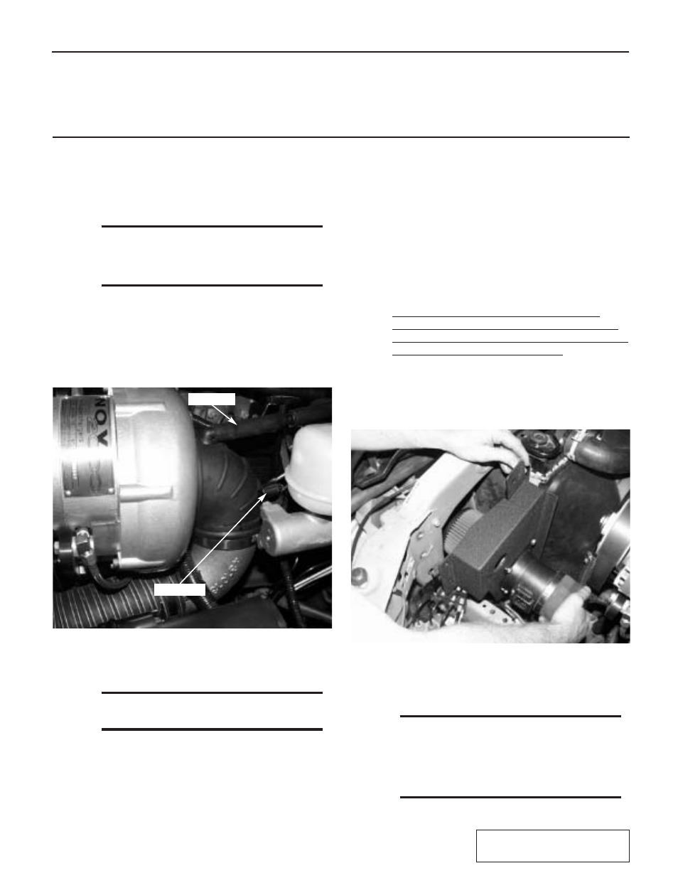
A.
Locate the supplied inlet duct Assembly
1015911 in the kit. Plug the air temp sensor,
previously removed in an earlier step, into the
open hole on the rubber elbow. (See Fig. 4.1-a.)
*** NOTE ***
Model year 2000 - engines will not have this sen-
sor. Install the supplied plug into the location
where the IAT sensor would be. It is recommended
that sealant be used on this plug.
B.
Slide the inlet hose with the attached aluminum
elbow in behind the supercharger and attach to
the inlet of the supercharger with the supplied
hose clamp. (See Appendix “F”.) The electrical
harness will go through the loop in the inlet
tube. (See Fig. 4.1-a.)
D.
Rotate the rubber elbow toward the engine until
there is clearance between the electrical con-
nection on the master cylinder and the elbow.
You will have to relocate the cruise control sen-
sor with the supplied TEE assembly for clear-
ance. Attach the flex hose to the aluminum
elbow. Next, connect the factory PCV hose into
the hose coming from the intake elbow. (See
Fig. 4.1-a.)
C.
Twist and rotate the elbow for the best possible
fit.
*** NOTE ***
The rubber elbow will point straight down, the
aluminum elbow will point outward slightly.)
IAT SENSOR
PCV HOSE
Section 4
SUPERCHARGER AIR INLET TUBE
A.
Locate the new air filter cover. Attach the new
air cleaner to the aluminum four bolt flange
adapter using the supplied hose clamp. Bolt the
air flow meter to the adapter flange sandwich-
ing the air filter cover in between. (See
Appendix “F”.) Next, use a razor blade or
sharp knife to remove the rubber flap with the
large hole in it (located on the core support next
to the radiator on the driver’s side). Fold the
other rubber flap against the side of the radiator.
This will help to seal the airbox. Remove the
three bolts that correspond with the mounting
holes in the filter cover and attach, re-using the
same bolts. (See Fig. 4.2-a.)
4.2
AIR FILTER ENCLOSURE
INSTALLATION
4.1
SUPERCHARGER INLET DUCT
B.
Slide the inlet hose onto the Air Flow Meter
and secure with supplied hose clamps. Plug in
the Air Flow Meter wiring harness.
*** NOTE ***
There is a large Venturi that goes in after the MAF
sensor. This Venturi actually increases bottom
and mid range torque while limiting the total
boost to 8 PSI. Removal of this venturi will make
your vehicle slower and subject the engine to
damage due to overboost.