Parts placement diagram, Step-by-step assembly instructions – Vectronics VEC-1500K User Manual
Page 55
50
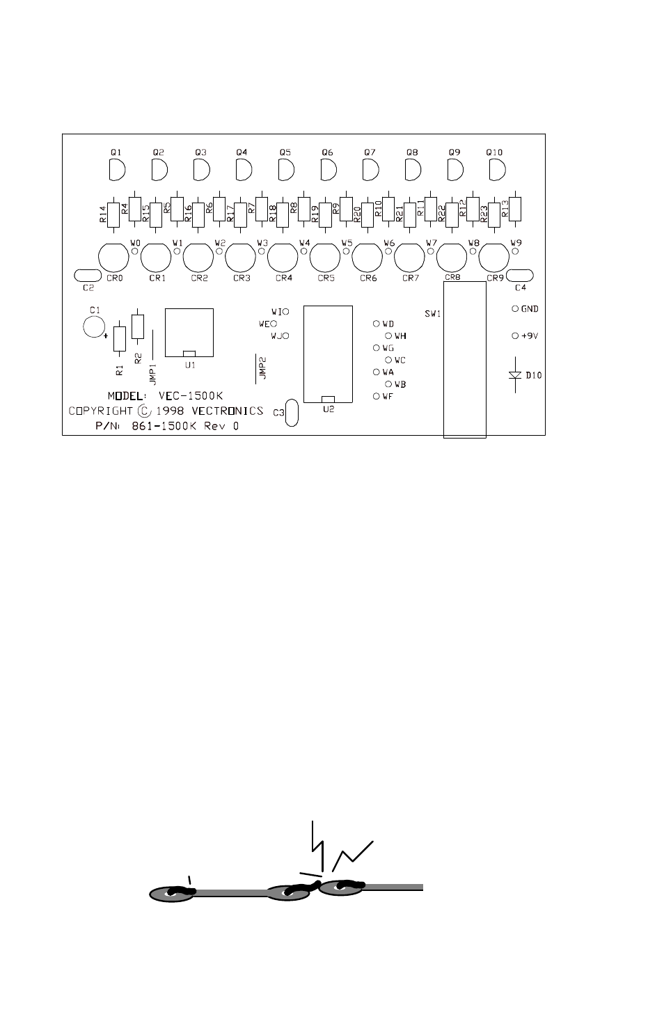
Parts Placement Diagram
Step-By-Step Assembly Instructions
First, a few notes and comments to help you along. Part designators for
components such as R1, C3, etc., appear in the parts placement diagram. The
parts are inserted on the top side of the board; traces are on the bottom side of
the board.
Install the monolithic (multilayer) capacitors so their values are easy to read
once all the parts are installed. Likewise, orient all fixed-resistor color bands in
similar directions. Doing so makes troubleshooting and verifying that no errors
were made during assembly easy.
In these instructions, when you see the term install, this means to locate, identify,
and insert the part into its mounting holes on the PC board. This includes pre-
bending or straightening leads as needed so force is not required to seat the part.
Once a component is mounted, bend each lead over to hold it in place. Use
sharp side-cutters to clip off excess lead length before soldering. Make sure
trimmed leads don't touch other pads and tracks, or a short circuit may result:
Good
Not Good