Vectronics VEC-1500K User Manual
Page 61
56
Install a 2N3904 transistor at location Q6. Solder.
Install a 2N3904 transistor at location Q7. Solder.
Install a 2N3904 transistor at location Q8. Solder.
Install a 2N3904 transistor at location Q9. Solder.
Install a 2N3904 transistor at location Q10. Solder.
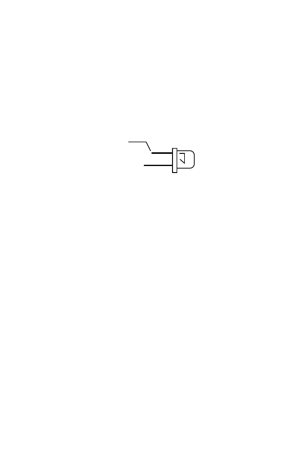
Locate the ten red LEDs. Observe that the cathode lead is the shorter of the two
device leads. The cathode lead is also indicated by a small flat area in the
otherwise round base of the device.
Cathode
LED
(shorter Lead)
The RED LEDs will be installed at locations CR0 through CR9 on the PC board.
Observe cathode lead orientation. All of the LED device bodies should be
mounted at the same elevation above the PC board surface. The leads of the
diodes are “shouldered”, these should set how high the LEDs sit above the PC
board.
Install a red LED at location CR0. Solder.
Install a red LED at location CR1. Solder.
Install a red LED at location CR2. Solder.
Install a red LED at location CR3. Solder.
Install a red LED at location CR4. Solder.
Install a red LED at location CR5. Solder.
Install a red LED at location CR6. Solder.
Install a red LED at location CR7. Solder.
Install a red LED at location CR8. Solder.
Install a red LED at location CR9. Solder.
Locate the eight-pin DIP IC socket. This is a “low-profile” style socket. Note
that the sockets are keyed to indicate pins 1 and 8. The key is either a “U” or
rectangular shaped notch. The parts placement will indicate proper orientation.