Vectronics VEC-1500K User Manual
Page 58
53
Install a 10K-ohm resistor (brown-black-orange) at location R10.
Solder.
Install a 10K-ohm resistor (brown-black-orange) at location R11.
Solder.
Install a 10K-ohm resistor (brown-black-orange) at location R12.
Solder.
Install a 10K-ohm resistor (brown-black-orange) at location R13.
Solder.
Carefully review your work. Make sure that locations R4 through R13 each
contain a 10K-ohm resistor. Examine all of the solder connections. Look for
unwanted solder bridges or poorly made solder connections.
Select ten 1K-ohm (1000 ohm) resistors (brown-black-red). These resistors will
be installed at locations R14 through R23 on the PC board.
Note:
save a few of the clipped resistor leads for later use as jumper
wires.
Install a 1K-ohm resistor (brown-black-red) at location R14. Solder.
Install a 1K-ohm resistor (brown-black-red) at location R15. Solder.
Install a 1K-ohm resistor (brown-black-red) at location R16. Solder.
Install a 1K-ohm resistor (brown-black-red) at location R17. Solder.
Install a 1K-ohm resistor (brown-black-red) at location R18. Solder.
Install a 1K-ohm resistor (brown-black-red) at location R19. Solder.
Install a 1K-ohm resistor (brown-black-red) at location R20. Solder.
Install a 1K-ohm resistor (brown-black-red) at location R21. Solder.
Install a 1K-ohm resistor (brown-black-red) at location R22. Solder.
Install a 1K-ohm resistor (brown-black-red) at location R23. Solder.
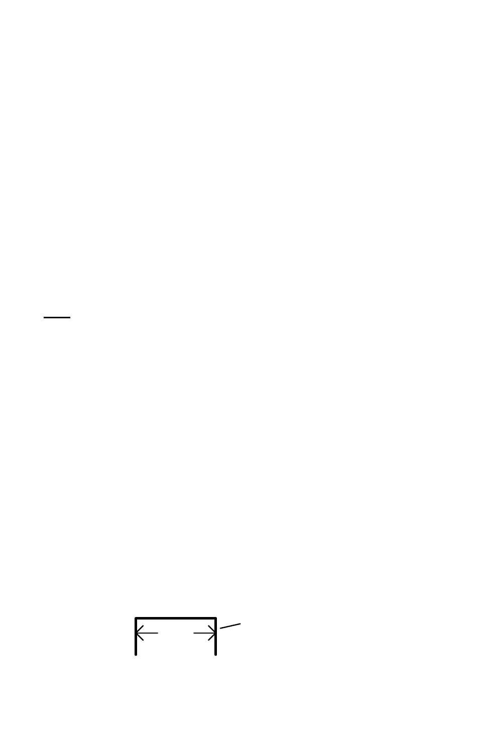
Select two of the discarded resistor lead clippings. Form both leads
to make jumper wires having a .3" span.
span
discarded lead end