Vectronics VEC-1500K User Manual
Page 56
51
The term solder means to solder the part's leads in place, and to inspect both (or
all) solder connections for flaws or solder bridges. Nip off excess protruding
leads with a sharp pair of side cutters.
Generally, it's easier to install small close-to-the-board parts first, and then
mount larger stand-up parts second. Delicate parts usually go on the PC board
last. Concentrate on your soldering while doing the assembly. Don’t attempt to
rush towards completion of the board--that only defeats the purpose of this
course.
Placing components:
To help you determine the proper location for each part
the manual contains a pictorial diagram showing the location of each part on the
PC board. Once again, the parts are inserted on the top side of the board; traces
are on the bottom side of the board.
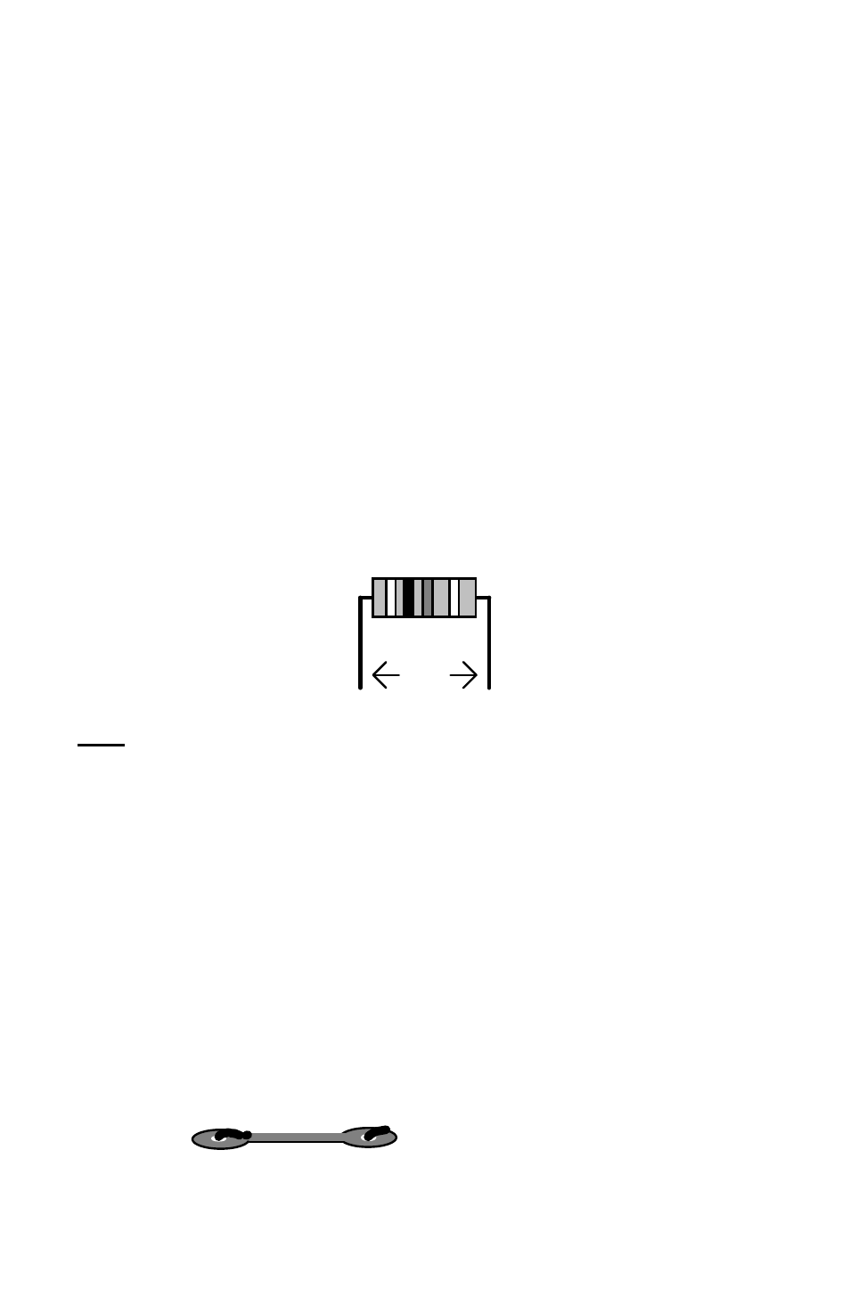
Assembly will begin with installing the ¼-watt fixed resistors. Because these are
all 5-percent tolerance, ending with a fourth gold color band, you need only read
the first three bands of the color code during the following steps. All resistor
leads should be formed as shown below:
.4"
Note:
Resistors are non-polarized devices. This means they may be
installed in any direction on the board. When assembling your
board, try to keep all resistor beginning and ending color bands
oriented in the same directions. This makes troubleshooting
easier, and also produces a neater looking board.
Locate a 1K-ohm (1000 ohm) resistor (brown-black-red). Form the
resistor leads as shown above, and install the resistor at location R1.
Use the parts placement diagram for assistance.
The body of the resistor should be resting flat against the PC board surface.
Gently bend the leads to hold the resistor package in place (see the example
below). Using a pair of fine cutting pliers, trim off the excess lead length.
Leads are bent over to provide a good mechanical connection before soldering.