Back, Panel, Diagram – Adtec digital DPI-1200 (version 01.04.08U) Manual User Manual
Page 23: Connections, Back panel diagram
channel
GPI Time
Changed
Displays the time the
most recent GPI
trigger received for a
channel
Non-editable display, status only.
Displayed in the format: Weekday
Hour:Minutes:Seconds:Milliseconds
(Day HH:MM:SS.mmm)
*.DPID GHS #
TIMENEW
GPO State
Sets condition of port
state for trigger
reception
OPEN Port is normally open
CLOSED Port is normally closed
(Front Panel Only Configuration)
*.DPID GPO #
DTMF
Speaker
Routes a given input
tone source to the
speaker on the
DTMF board
ON Turns on speaker for DTMF
Tone for channel
OFF Turns off the speaker for the
channel
*.DPID SRP #
Note: Up to twelve Insertion Channels are available on the product. If using API
Commands, the ‘#’ denoted in the commands above are relevant to the twelve channel
destinations indexed 0 - 11.
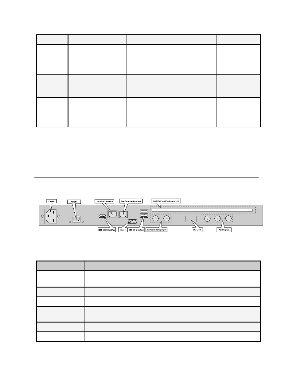
Back Panel Diagram
The back panel contains the ports and connection points for the device.
Connections
Connection
Function
AC Power
AC Power- standard 3-pin plug (70-240 VAC 50-60 Hz), 5Vdc Power
(x2) - External Power Only
GigE
GigeE Interface - MPTS Output over UDP / Management
Firewire
FireWire Reserved for future use
Terminal Monitor
API Serial Communication Interface / Serial Port used for
Troubleshooting
Fast Ethernet
10/100 base T-Ethernet interface
RS232
DB9; Used to communicate with redundancy switch (ASI Model Only)