BECKHOFF BC3100 User Manual
Page 14
Basic information
14
BC3100
and, depending on the field bus, into the process image.
Process image allocation
By default, all terminals are allocated to the process image of the PLC task
(beginning with the address %Q*0 or %I*0) but, via the configuration
interface, the peripheral signals can also be allocated terminal by terminal
to the field bus process image, with the result that they would be
transmitted directly via the field bus without pre-processing by the PLC
task.
Default assignment of
inputs and outputs to the
process image
When the BC3100 is first switched on it determines the number of attached
bus terminals and sets up a list of assignments. This list distinguishes
between analog channels and digital channels and between input and
output; which are grouped separately. The assignments begin immediately
to the left of the BC3100. The software in the bus coupler creates the
assignment list by collecting the entries for the individual channels one at a
time, counting from left to right. These assignments distinguish four groups:
Function type of the channel
Assignment level
1.
Analog outputs
byte-wise assignment
2.
Digital outputs
bit-wise assignment
3.
Analog inputs
byte-wise assignment
4
Digital inputs
bit-wise assignment
Analog inputs/outputs are representative of other complex multi-byte signal
bus terminals (RS232, SSI sensor interface, ...)
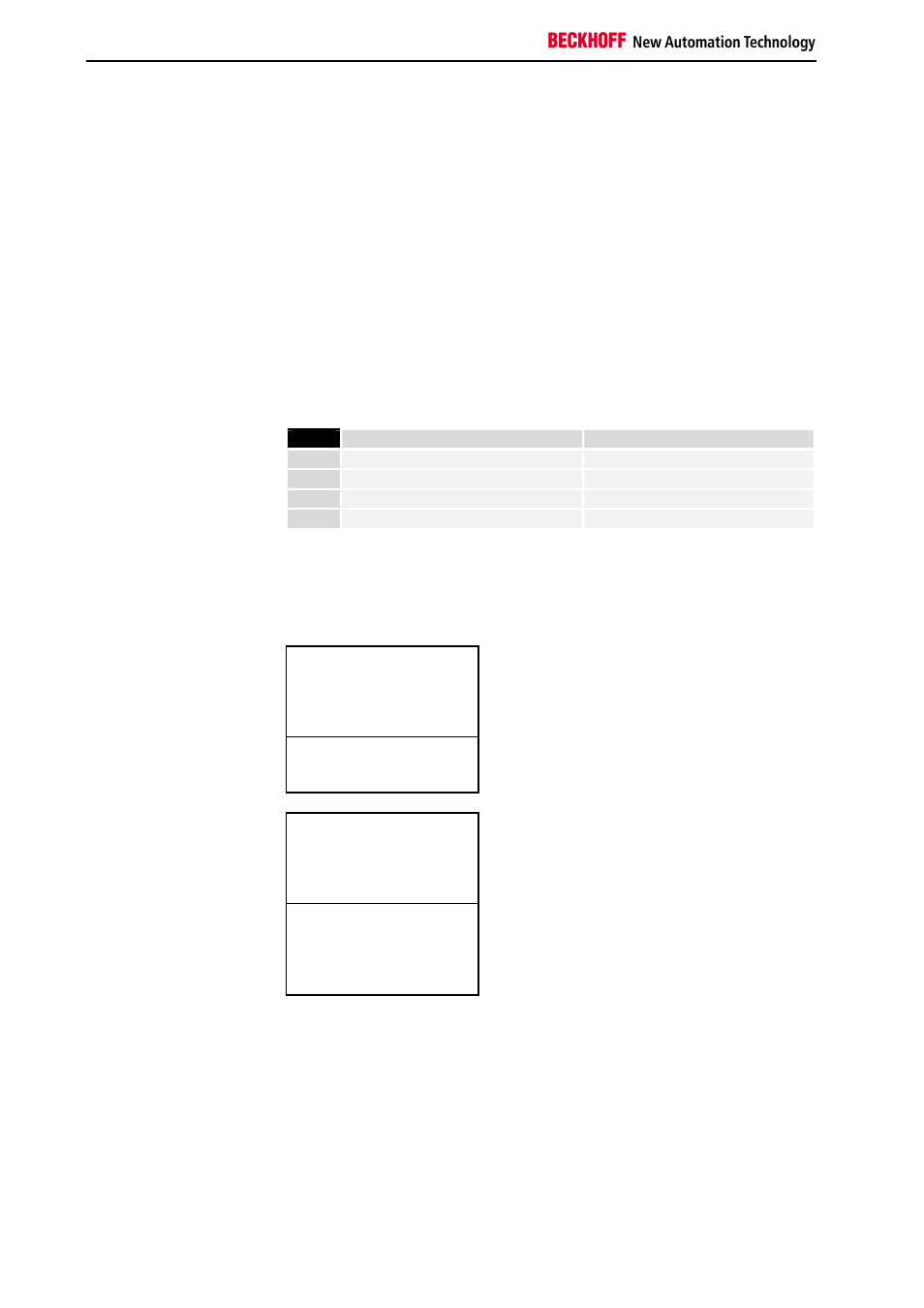
Overview of the subdivision of the process image in the BC3100
Output data in the BC3100
O0
...
byte-oriented data
...
Ox
Ox+1
bit-oriented data
Ox+y
Input data in the BC3100
I0
...
byte-oriented data
...
Ix
Ix+1
...
bit-oriented data
...
Ix+y
Assignment of the process
image of the PLC task to
the field bus process image
Depending on the setting, the affiliations between the inputs and the
outputs of the PLC task and the field bus process image are defined
automatically by the BC3100 via the configuration interface or by
programming. When assignments are programmed, inputs and outputs can
be distributed bit by bit in any order to the field bus process image. This is
set manually with the configuration interface or, depending on the field bus
functionality of the bus terminal controller, with the TwinCAT System
Manager at the variable level.
By default, automatic assignment is set for the bus terminal controllers. In
this case, one coherent area each of the inputs or outputs of the PLC task
can be mapped into the field bus process image. The initial offset and