Assignment of terminals in the integrated plc – BECKHOFF BC3100 User Manual
Page 47
Annex
BC3100
47
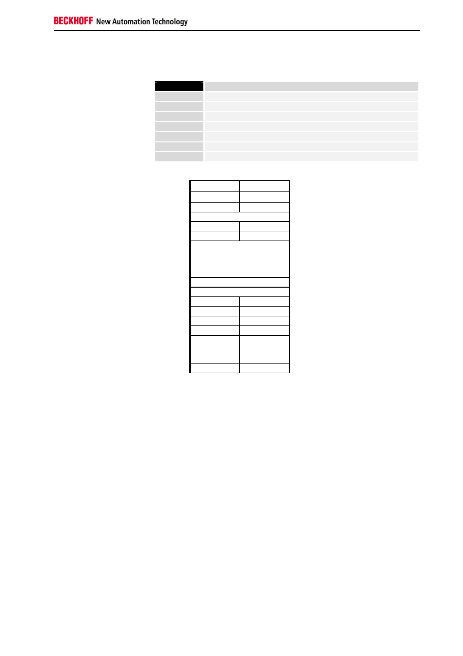
Meanings of the control/status byte for access to the register model:
BIT 7
0 = NORMAL MODE, 1 = CONTROL MODE
BIT 6
0 = READ,
1 = WRITE
BIT 5
Register address, MSB
BIT 4
Register address
BIT 3
Register address
BIT 2
Register address
BIT 1
Register address
BIT 0
Register address, LSB
Register set of an
63
analog channel
47
31
15
User area
16
0
OFF SET
GA IN
Manufacturer settings
SoftwareVer
s
Type
0 Length
Type
Auxiliary process image
The meanings of the registers and of the status bytes are explained in the
corresponding data sheets of the bus terminals. As far as its design is
concerned, the module is identical for all bus terminals with more extensive
signal processing.
Assignment of terminals in the integrated
PLC
By default, in a delivered version of the BC3100 all terminals are assigned
to the integrated PLC. As far as mapping of the terminal signals to the PLC
process image is concerned, what has been said above applies. The first
channel of the first analogue terminal is located at offset 0, in each case for
inputs and outputs. By default, the complex terminals are mapped
completely and in the INTEL format. As the 80161 processor of the
BC3100 can only address words at even addresses, the terminal data is
stored in the process image with word alignment.
Example:
1. KL1002
2. KL2012