Annex – BECKHOFF BC3100 User Manual
Page 42
Annex
42
BC3100
Annex
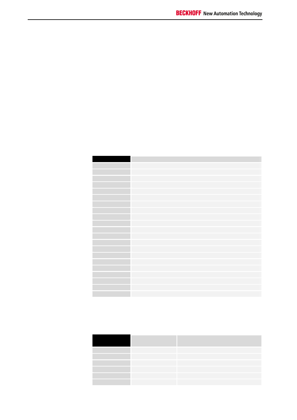
Example: a process image in the bus
terminal controller
An example explains the assignment of the input and output channels to
the PLC process image. The example set up is to consist of the following
bus terminal modules.
Whether the data of the analog terminals is to be evaluated completely (i.e.
with control/status byte), or whether only the user data is evaluated, is set
in the bus terminal controller. Evaluation with control/status byte (complete
evaluation) is the default.
In this configuration, the bus terminal controller creates the following
allocation lists:
Position
Function module on the rail
POS01
Bus terminal controller
POS02
Digital inputs 2 channels
POS03
Digital inputs 2 channels
POS04
Digital inputs 2 channels
POS05
Digital inputs 2 channels
POS06
Digital inputs 2 channels
POS07
Digital outputs 2 channels
POS08
Digital outputs 2 channels
POS09
Digital outputs 2 channels
POS10
Analog inputs 2 channels
POS11
Analog outputs 2 channels
POS12
Analog outputs 2 channels
POS13
Analog inputs 2 channels
POS14
Infeed terminal
POS15
Digital inputs 2 channels
POS16
Digital inputs 2 channels
POS17
Digital inputs 2 channels
POS18
Digital outputs 2 channels
POS19
Digital outputs 2 channels
POS20
Analog outputs 2 channels
POS21
End terminal
Analog terminals with user data only (no default setting)
All terminals are assigned to the process image of the PLC task. Analog
terminals are mapped with user data only. Part for byte-oriented outputs:
Position in
block
PLC task
Process image
Description
POS11
QW0
Output signal 1
st
channel
POS11
QW2
Output signal 2
nd
channel
POS12
QW4
Output signal 1
st
channel
POS12
QW6
Output signal 2
nd
channel
POS20
QW8
Output signal 1
st
channel
POS20
QW10
Output signal 2
nd
channel